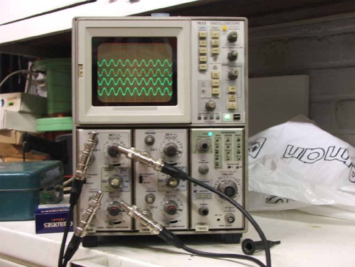
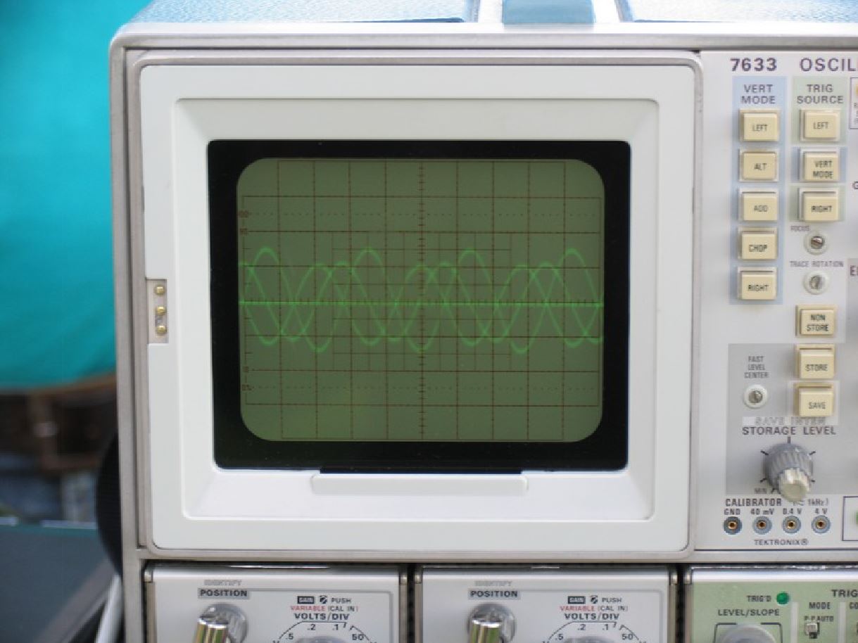

Never mind the amplitude, we got it right but we don't have a picture of it. What is clearly visible, is the perfect phasing interaction : 0, two times -90, and once -180 degrees.
|
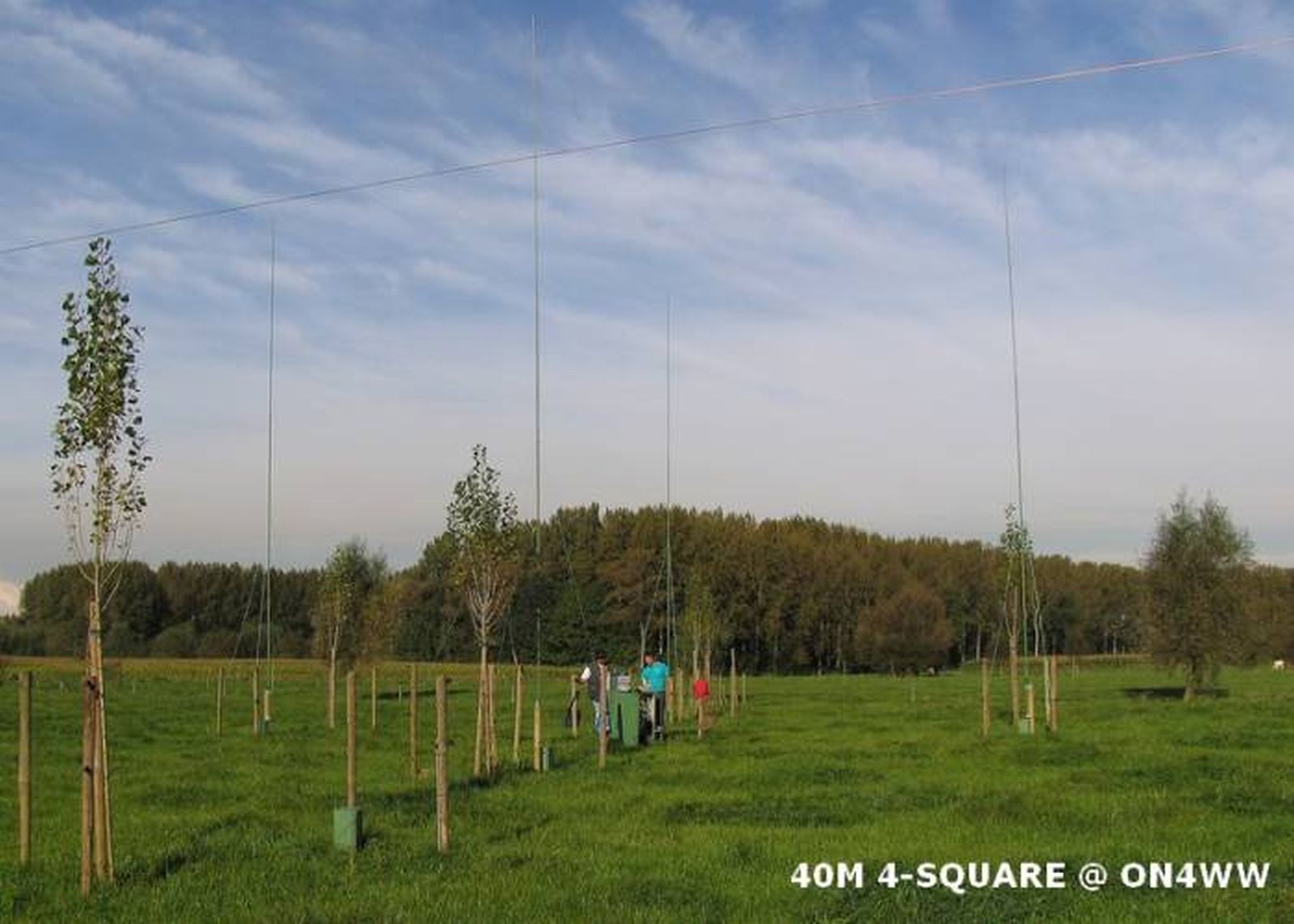
The 40m 4-square on a 4-channel Oscilloscope
|
August 2005. Fieldday preparation for our clubstation took me to the aluminum
dealer. Hey, instead of just buying aluminum for the club, why not buy some
more and make the verticals for the 40m 4-square ? Done.
September 2005. The verticals are ready and painted, the 40m 4-square hybrid
coupler installed in the central cabinet. Plug and play ? Yes, plug and play.
The beauty worked flawlessly from day one ! 15 radials per vertical are used,
of each 5m length. I did tests with 5, 10, 15, 20 and 25 radials, and decided
to go for 15 as they have to be removed for the farmer's needs when necessary.
The >20dB F/B is present, and impressive. The 4dB gain over a single vertical
is impressive. It varies between 1 to 3 S-points in real life !
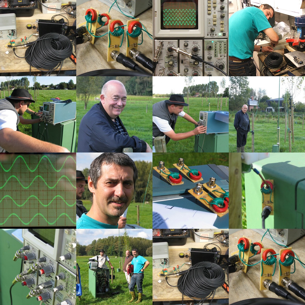
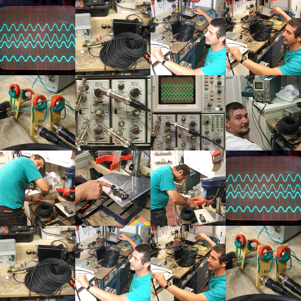
Karel ON5TN is a man with a plan. He wanted to visualize the 4-square's performance on a 4-channel oscilloscope. Problem, nobody he knew had a 4-channel scope. Well, good old flee market came to his rescue. Karel went to a local ham flee market on Sunday 2nd October 2005. He found a working model 7633 Tektronix 75 MHz 4-channel oscilloscope for 100 Euro. Is that a bargain or what ?! He also found four RG58 cables of identical lengths with BNC connectors, BNC T-connectors, 50 Ohm BNC end-plugs. In short, he found everything necessary for the tests, on that flee market !
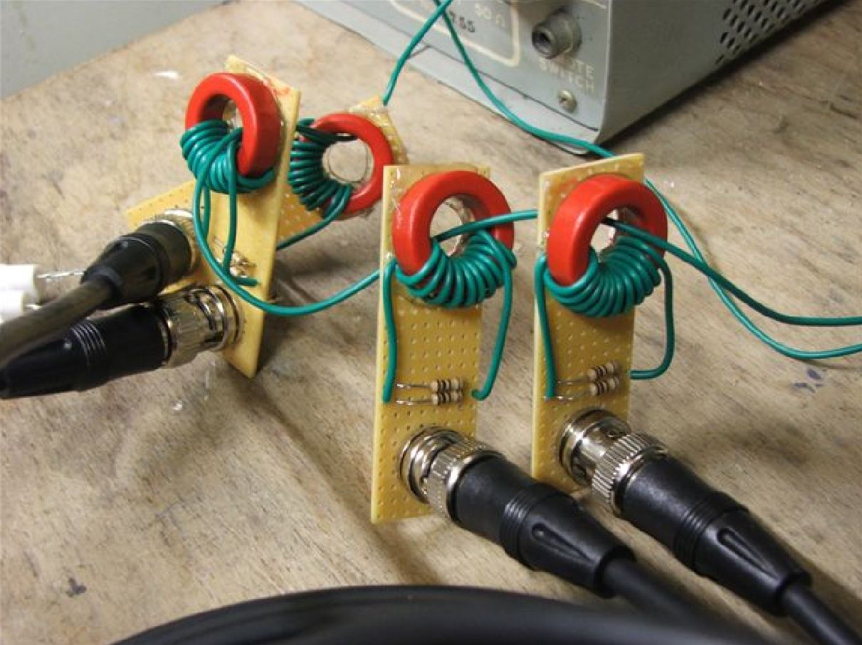
Already that same evening he came over and we worked until well after midnight, preparing four RF current probes. Karel found the idea for the test on Greg W8WWV's website. Greg uses the oscilloscope to make phased array measurements, and got Karel enthusiast to give it a try on my 4-square. Here's how Greg's RF current probes look like.
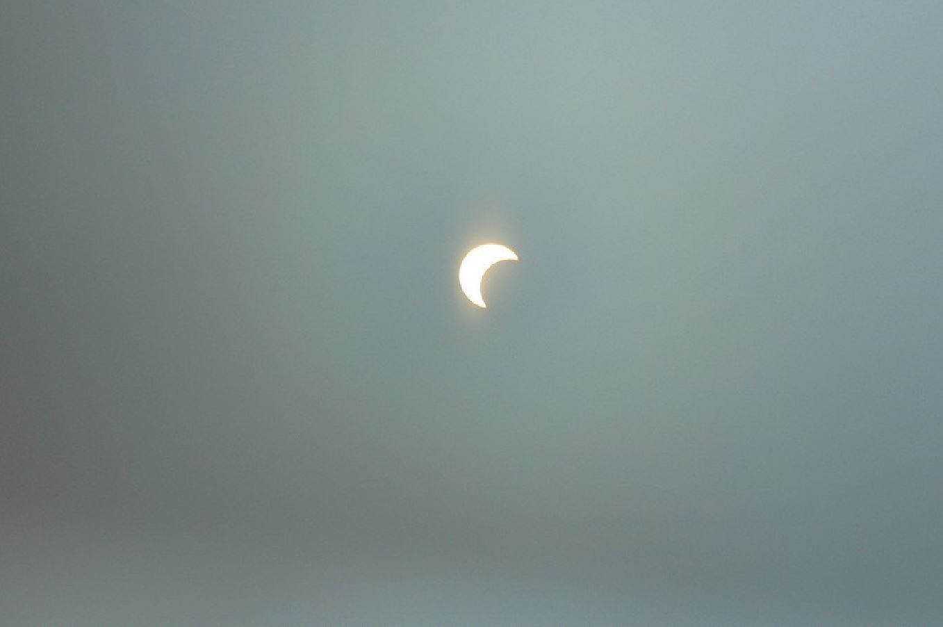
The following day we did the measurements. It was exciting to see the 0, -90 and -180 degree phasing come up on the screen as it should ! It was also exciting to experience the partial solar eclipse that day ! Marc ON4MA and John ON4UN joined the party. Truly a fine ham radio day. Congrats to Karel in pursuing his goals !
Click on the following photographs, courtesy ON4MA and ON5TN, to see the full size pictures.
|
|
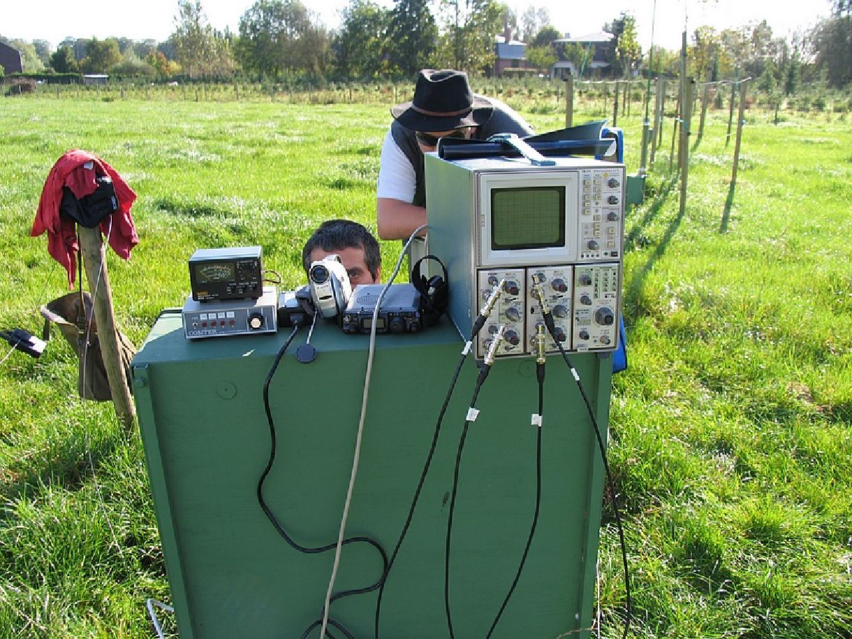
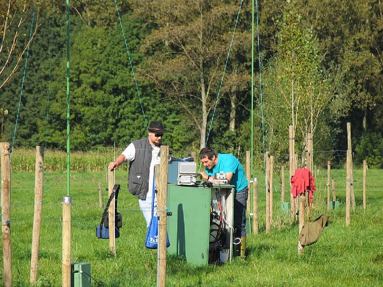
Overview of field tests with the Oscilloscope |
|
|
Preparatory works in the garage, testing the Oscilloscope |
|
|
The 40m 4-square. Notice the SW Beverage in front, which was put up for the K7C expedition long path openings. |
|
|
RF current probes under test in garage |
|
Testing the RF current probes with four equal lengths of RG58 coaxial cable, using an FT-817ND as RF generator (we also used the MFJ-259B, works equally well) and an old Collins DL-1 dummy load |
|
|
Waw, 100 Euro for this Tektronix 7633, and it works ! |
|
|
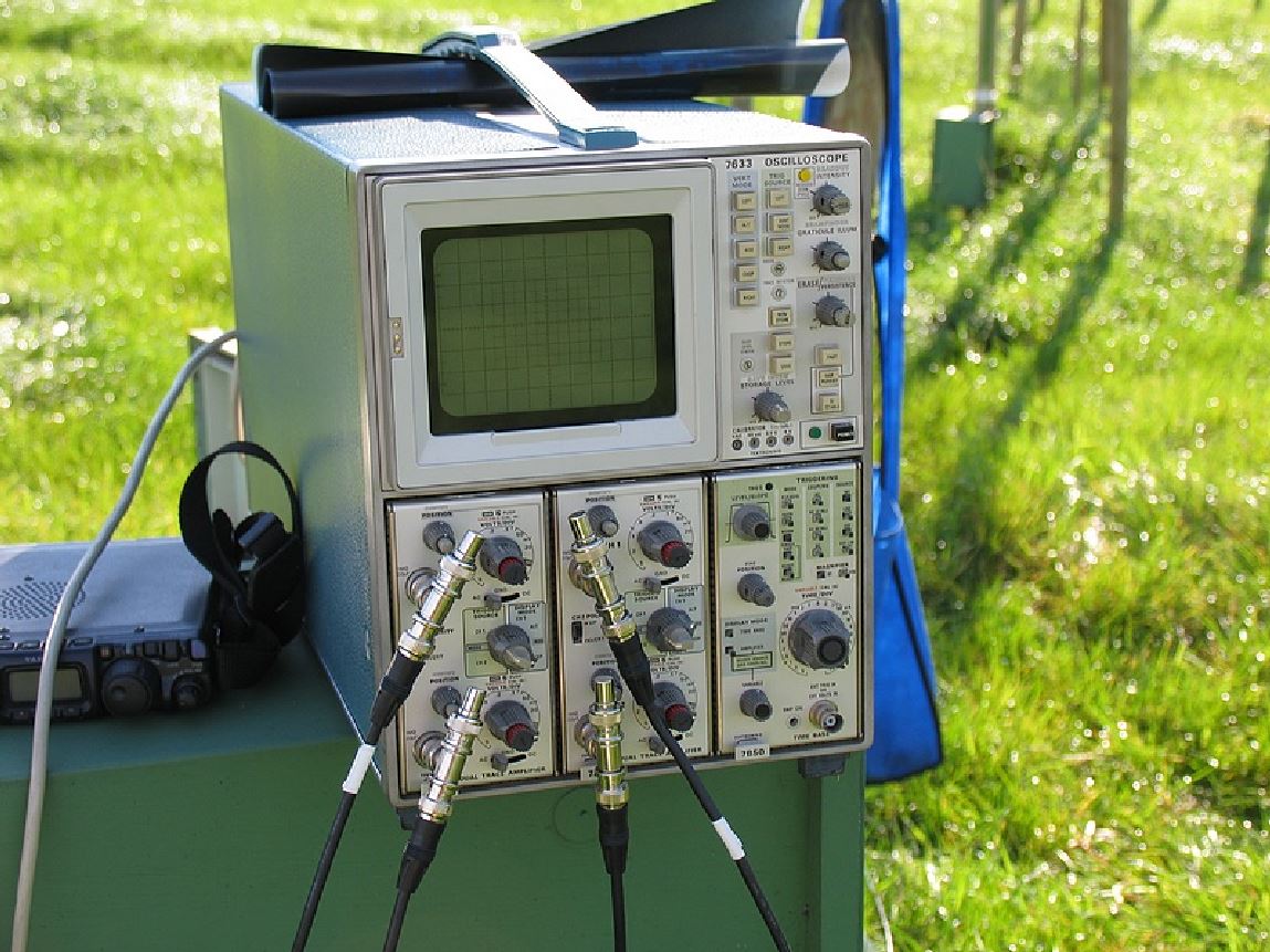
The 4-channel Tektronix Oscilloscope on the central cabinet in the field. Notice the four coaxial cables connected to the BNC T-connectors, and the 50 Ohm end plugs. The four cables go to the individual 40m quarter wave verticals of the 4-square |
|
|
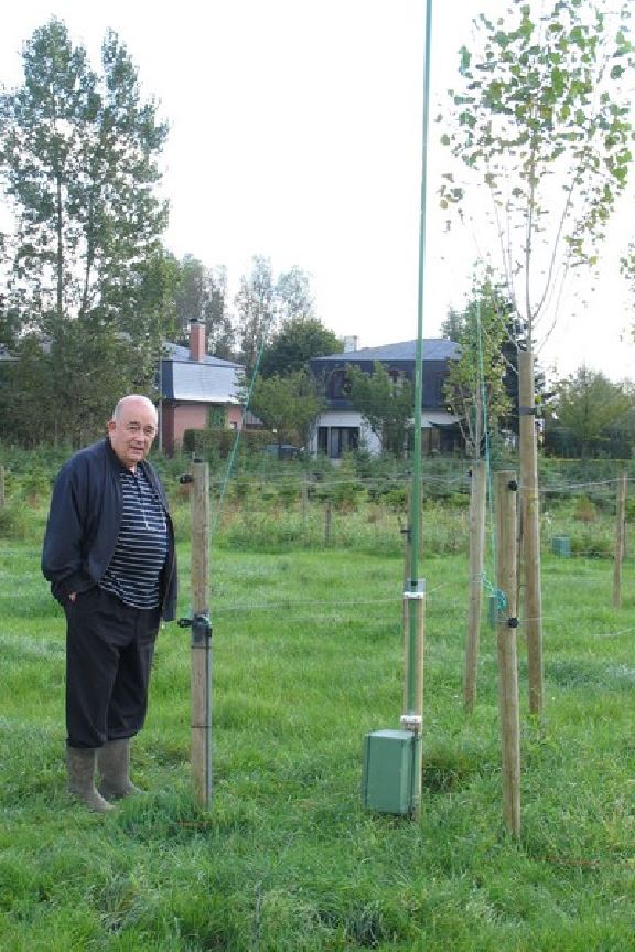
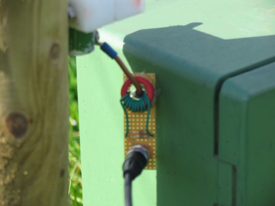
Here's John ON4UN at one of the verticals. The bottom of the vertical is connected through a small electrical wire to a screw at the top side of the green cabinet. The cabinet houses another piece of electrical wire which is soldered to an SO-239 connector. Plenty of room inside the cabinet to install matching networks (which may be necessary for the 80m 4-square, the 40m 4-square covers the entire band without matching |
|
|
The picture isn't very sharp quality, but it shows the small piece of electrical wire connected to the cabinet. We slid the wire through the RF current probe for test purpose |
|
|
The complete test setup. The Revex power meter was used for another test that day. About 160m of 7/8 hardline goes to the shack. 100W out the shack, gave 100W at the central cabinet on 160m, and 75W on 10m band...not bad ! Below the Revex is the ACB-4 Comtek array switch. Then the FT-817ND used as RF generator, and the Tektronix |
|
|
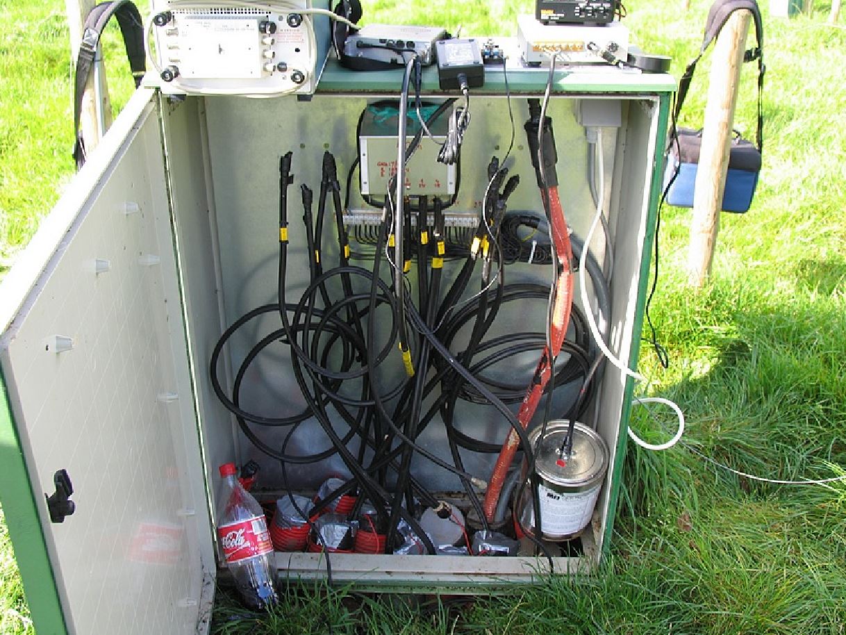
Inside the central cabinet. Top right, 220V outlet. Bottom right, dummy load. Red colored 7/8" 50 Ohm hardline to the shack (160m away). Top middle, the Comtek ACB-4 Hybrid Quadrature Phasing Coupler. Below that, 30 individual 1.5mm electrical wires going to the shack, for multipurpose use (switching relays etc...). Twelve 75 Ohm phasing lines entering cabinet at bottom. Left and right of 40m coupler, are the 80 and 160m cables ready for use. These couplers are not yet installed |
|
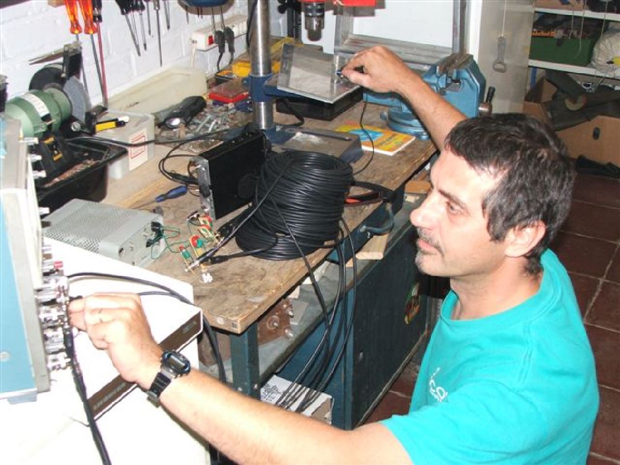
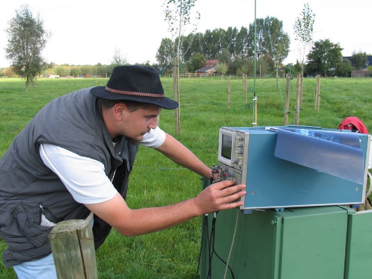
Karel ON5TN. This is his project, very well done ! Here he's adjusting the Oscilloscope to display the phasing delays |
|
|
All four lines displayed in center |
|
|
Never mind the amplitude, we got it right but we don't have a picture of it. What is clearly visible, is the perfect phasing interaction : 0, two times -90, and once -180 degrees. |
|
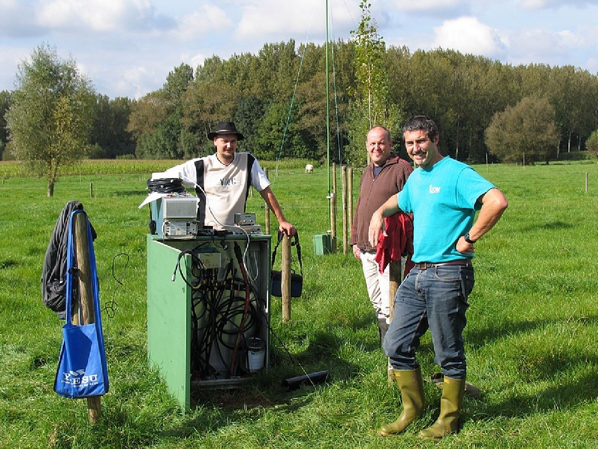
ON5TN and ON4WW |
|
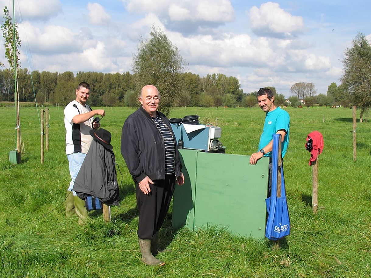
ON5TN, Marc ON4MA and ON4WW. Marc has been testing a lot of different antenna systems at home, and had to see this experiment. |
|
John ON4UN is always interested and helpful when things get serious. Just when we were wondering why we didn't see a double amplitude on one of the signals, John arrived and explained that with quadrature coupling, all amplitudes are equal. The picture with double amplitude on W8WWV's website is when measuring his HEX array |
|
A perfect day for antenna measuring tests, topped with a clear blue sky which allowed us to observe the solar eclipse during our tests ! It doesn't get much better than this, believe me ! |
|
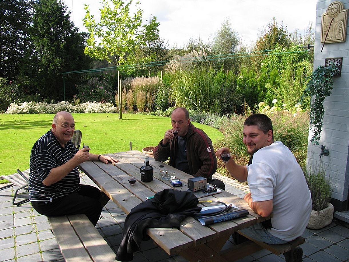
What we missed on the field during testing, we drank on the terrace afterwards. One bottle of port wine down, up to the next experiment... |