On October 3d 2005 - a beautiful autumn day with a partial solar eclipse - we did the following tests with a 4-channel Oscilloscope. A must see !
|
The triple 4-SQUARE Project
|
Spring 2004. The 4-square project was lingering on my mind already for a couple of years. Being back home for a longer while, this was the time to go ahead and start working on the long-term 4-square project.
Long-term, because I want to suspend the verticals from trees. And trees need time to grow. I guess in a couple of years the trees for the 40m 4-square will be tall enough, the 80m and 160m 4-squares will take a bit longer ;-
The preparatory work is finished. Cutting the 12 quarter wave 75 Ohm coaxial feed lines to exact lengths and put connectors on them, prepare the 12 small cabinets where the verticals will be attached to, digging a couple of hundreds of meters of one meter deep trenches, etc...
As one can see on the photographs, the 40m 4-square will be centered in the 80m one, which will be centered in the 160m 4-square. Hence the 'Triple 4-square'. Can't wait for the trees to grow....
Karel ON5TN was so eager to do some tests on 4-squares, I decided to buy aluminum
and prepare the 40m 4-square for him.
On October 3d 2005 - a beautiful autumn day with a partial solar eclipse - we
did the following tests
with a 4-channel Oscilloscope. A must see !
Fast forward year 2016 to 2020
Radials
Although the trees were growing, it became clear they would never reach the
clouds. Time for some action.
In 2016 and 2017 - with the help of several local hams (on1bej, on5tn, on6yn,
on7asn) - the radials were installed 10cm below ground surface. Interesting
exercise, see the photo's and video's further down. We aimed at 15 radials of
1/8th wavelength per vertical. This goal was reached with the 40m 4-square.
For the 80 and 160m 4-squares, some of the radials were shortened to avoid overlap
(otherwise we would have cut the already buried radials). The radials are not
electrically connected near the overlap points. The radials of two of the 160m
verticals (close to the neighbouring fields) could not be laid out across 360
degrees, but only 180 degrees. The radials' aerial overview photo further down
below, is self-explanatory.
The 180 radials (15 radials/ant x 12 antennas) consist of 1mm insulated wire
(wire gauge 18).
Wire verticals
Next up were the verticals, 2018 into 2019: on4ma, on5uk, on6yn and my son were
instrumental for this part. All verticals are wire verticals, suspended from
a threaded rod/pulley/rope support at 12m height.
The 40m 4-square comprises of full size wire verticals of 2.5mm (wire
gauge ± 10), length 9,70m.
The 80m verticals: first tested with an inverted-L, but settled for shortened
verticals with capacitance hat (per the ON4UN Low-Band DXing book and KB0FHP
description), diameter 1.5mm (wire gauge ± 15). Length of the vertical
part is 11,89m, each leg of the capacitance hat is 5,80m.The capacitance hat
legs are not in a straight line, but are drawn beside and towards the back of
the tree. Their interaction with the tree (capacitive effect) makes for a perfect
match to the Comtek hybrid coupler (yep). Another advantage (although many will
argue the first 'advantage' is not really desired nor an advantage) is that
the whole construction can be attached to the tree - agricultural machines and
cattle have free passage in summer time.
I first experimented with a hairpin match (2.9 uH coil) at each vertical to
reach optimal impedance, but abandoned that approach when I discovered the 'interaction
trick between capacitance hat legs and tree'. The system stays stable year round
(give or take a maximum up/down shift of 30 kHz - flowing tree sap and closeby
leaves in summer). To switch from SSB to CW, at the bottom of each vertical
a 2.465uH coil is switched in with a relay (Finder 65.31.9.012.0000). The end
points of the T-legs (capacitance hat), are at a (horizontal) distance of 2.5m
from the vertical part of the antenna. Different distances (=different angle
of the legs) made for different impedances. It's a matter of finding the 'sweet
spot'.
The 160m verticals are inverted-L's comprising of 1mm wire (wire gauge
18), length 39,70m (12m vertical part, 27,70m sloping down to a height of ±
7m). I experimented with L-matching networks to provide an acceptable match
for the hybrid coupler, but in the end settled for 37.5 coaxial lines (see further
down). The impedance of the two 160m inv-L's with radials only 180 degrees across,
slightly differs from the other two with a 360 degree radial coverage. This
posed no problem in regard to the matching towards the hybrid coupler.
The 80 and 160m wire diameters are smaller than the 40m antennas for consideration
of weight. We experienced several storms since the wire verticals are up, they
have learned me a thing or two. Weight does matter...
I had to install thicker diameter wire at the sections where the wires touch
the insulators (heavy friction during storm winds).
Tuning of the antennas
All verticals were tuned with the MFJ-259B. A double check was done with an
AA-230 Zoom RigExpert and a Mini-VNA, same results.
40m was pretty straightforward, 80m and 160m less so. A lot of time was spent
experimenting on 80m with the T-legs (capacitance hat). On 160m I experimented
extensively with the end positions of the sloping horizontal part of the inverted-L's.
Also experimented by adding more radials (kept it at 15 radials per vertical).
The measurements and construction of the antennas were done in all kind of wintery
weather conditions... sun, rain, heavy winds, snow, frost... it added to the
fun !
Comtek ACB-4 hybrid couplers
The three 4-squares use Comtek ACB-4 hybrid couplers. These couplers are very
forgiving and match the wire antennas wonderfully well. No reflected/dumped
power on the 40m 4-square (except 2% near the edges of the (Region 1) 200 kHz
band). On 80m a coil is switched in to cover the CW portion of the band. Less
than 2% reflected power at the edges of the band. On 160m, there is 30 kHz of
bandwidth (5% dumped power at 30 kHz edges), which suits me perfectly (no dumped
power at 1828 kHz).
On 40m, with the full size wire elements, the upward shift in frequency is 100
kHz due to mutual coupling (each vertical needs to be tuned to 7.000 kHz, in
order for the 4-square to end up on 7.100 kHz). The Comtek manual states that
with wire verticals, the mutual coupling may be reduced - I did not witness
this, the 100 kHz upward shift is smack on.
On 80m, the shortened verticals with capacitance hat have an upward shift of
70 kHz (each T-vertical resonant near 3680 kHz).
On 160m, with the low inverted-L's (12m height), the upward shift is only 20-25
kHz.
The 80-160m upward shift observations correspond with the Comtek manual (shortened
verticals => less mutual coupling).
Different matching coaxial lines
On 160m, I experimented with matching L-networks at each vertical (because of
a low R of 14), but abandoned this approach. Instead I changed the 75 ohm coaxial
lines to 37.5 ohm lines (by parallelling two 75 ohm lines and using T-connectors)
(the Comtek manual states to use 50 ohm lines for inverted-L's to accomodate
for the lower impedance of such antennas).
On 80m I experimented with 50 ohm lines, but in the end kept the 75 ohm lines.
The impedance could be adjusted by varying the angle of the T-legs, and their
distance to the tree (the closer to the tree, the higher the impedance - empirical,
not very scientific, but it works).
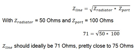
A wealth on information about hybrid couplers and matching lines can be found
in this
outstanding article by DF6QV. On page 47 is the formula which calculates
the impedance of the needed coaxial line. Since I had a very low impedance on
my 160m radiators, I ended up with the 37.5 ohm lines. My Zradiator was about
15, the Zport of the Comtek hybrid coupler is 100, which results in a Zline
of 38.7, which called for the 37.5 ohm lines. Here is the formula (for the ideal
situation of a 50 ohm impedance):
Interaction between the 4-squares
What surprised me most, is that there is (almost) no interaction between the
three 4-squares. I did extensive testing on 40-80-160 by lowering each and all
verticals, while monitoring each vertical separately. The R/X figures barely
moved on the MFJ-259B ( perhaps one unit, but that also happens when the wind
moves the wires, and it was often windy when I did measurements). The Comtek
manual states not to install a 40m 4-square into an 80m 4-square, 80 not into
160 etc.- '40m performance will be greatly reduced due to mutual coupling'.
It seems that this is not the case (or minimal) when using shortened wire verticals/inverted-L's
on 80/160m (full size, 'fat' verticals are of course a different ballgame).
It is in the planning to do these interaction tests again one sunny day, with
more sophisticated equipment. My feeling however is that my little ol' 259B
has it right. In this regard, also see the next paragraph.
The proof of the pudding is in the eating
The 4-squares have been in operation since spring 2019.
I have done extensive A/B testing between the 4-squares and my single element
verticals (40m 1/4wl vertical, 80m shunt-fed tower (12m height), 160m inverted-L
at 12m height (with which I worked 309 entities on topband, something gives).
These single element antennes are near the house, and about 100m away from the
4-squares.
As already noted during our testing
in 2005 with the 40m 4-square: "The >20dB F/B is present, and
impressive. The 4dB gain over a single vertical is impressive. It varies between
1 to 3 S-points in real life !"
Depending on the arrival angle/polarisation of the signal, the same behavior
is observed on the three 4-squares. Sometimes there is a reduced F/B, but most
of the time it is just impressive. The forward gain is observed again and
again when compared to my single element verticals.
On 31 March 2020 I did once more a transmit A/B comparison on 160m with Don
N1DG. Don said 'wow' and noticed a 'consistent 15dB advantage' in favor of the
4-square. Conditions were good that night, the inv-L was at S9 level on Don's
radio, the 4-square at S9+15dB.
I also remember working someone in South Europe on 80m last year, when he asked
me to switch the array to the back. This ham was vy strong with me (S9++), and
completely disappeared when switching the array 180 degrees.
These 2 examples are somewhat exceptional. Most of the time the differences
are more moderate. But still vy impressive compared to a single element vertical.
Hope you appreciated reading this account on the triple 4-square project. It is not all rocket science, but it gives an impression on what can be achieved.
Click on the photographs to see the full size pictures.
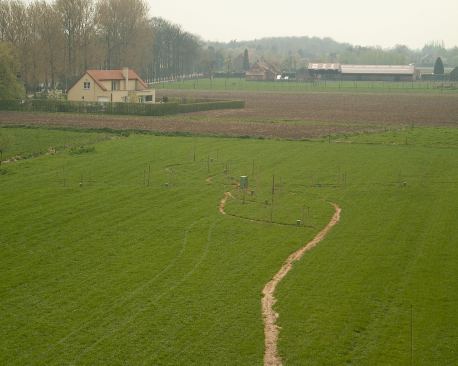 |
The hard work is finished, let the trees grow, let them grow ! This is an aerial overview with the layout of the triple 4-square clearly visible |
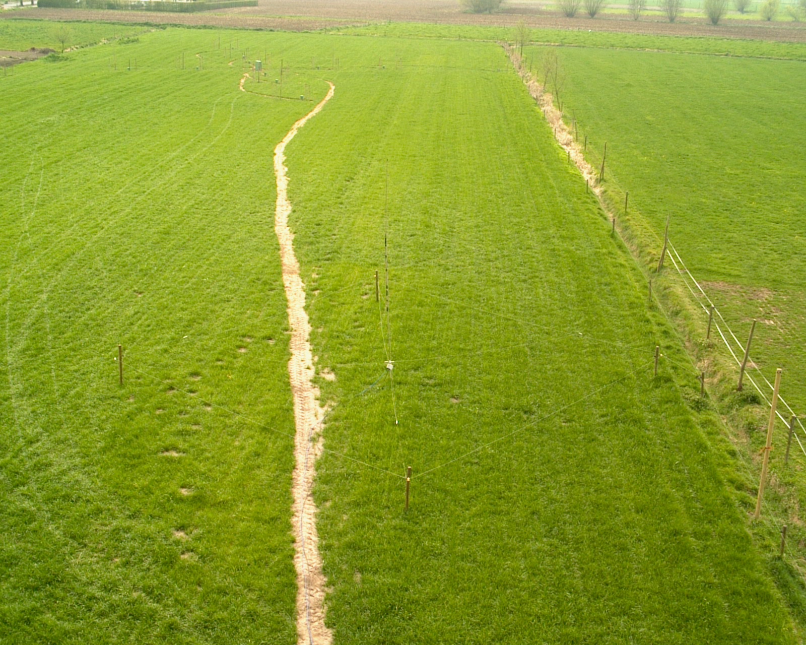 |
On the right hand side foreground, one can notice the K9AY array. At the back of the field one can see the triple 4-square array |
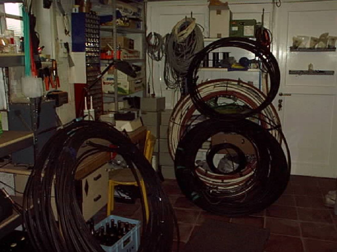 |
Preparation. Preparing four quarter wave 75 Ohm feed lines for 40m, four
for 80m and four for 160m. Trimming to correct lengths and putting connectors
on takes a while. These feed lines go from the central hybrid coupler to
each of the verticals. Also visible in the back, upright, is 135m of 7/8" hardline 50 Ohm coaxial cable |
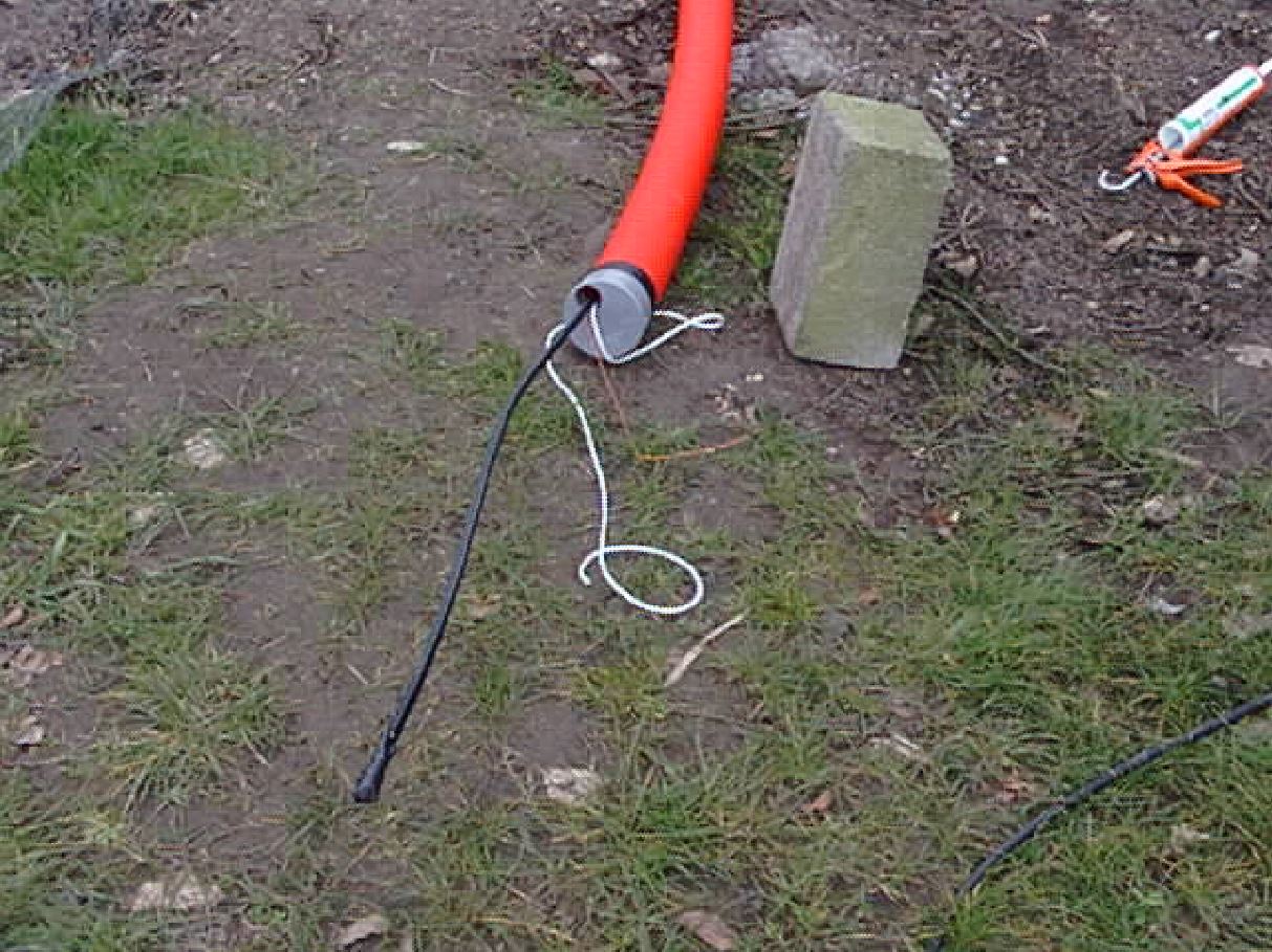 |
The finished feed line goes inside red plastic tubing. Note the white pull-cable, which can be used at any time to pull in extra cables for relay switching etc... |
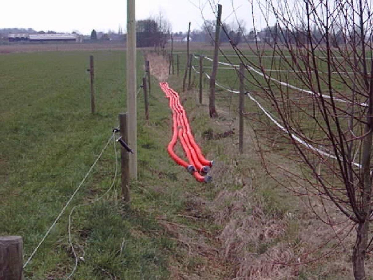 |
Four 160m feedlines are finished |
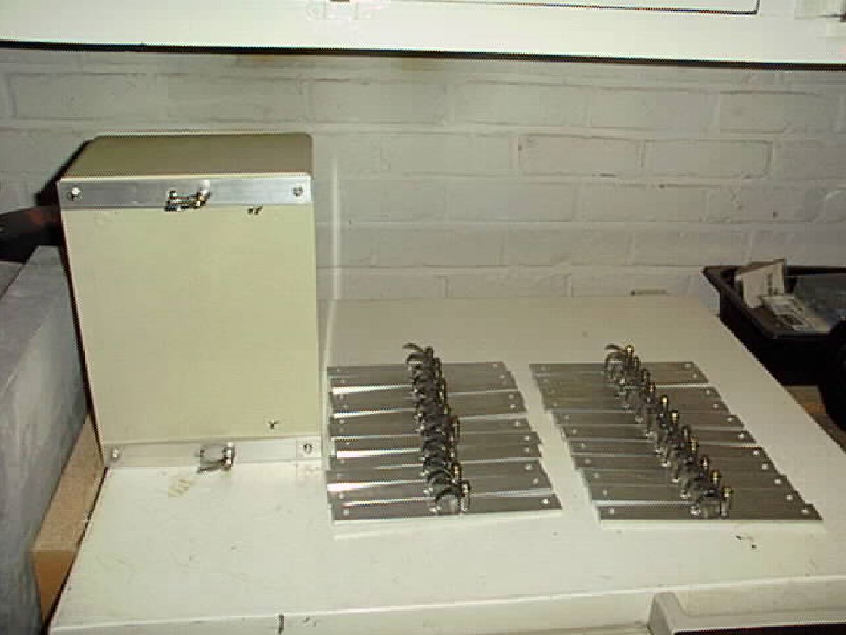 |
Preparing 12 cabinets which will be placed at each vertical |
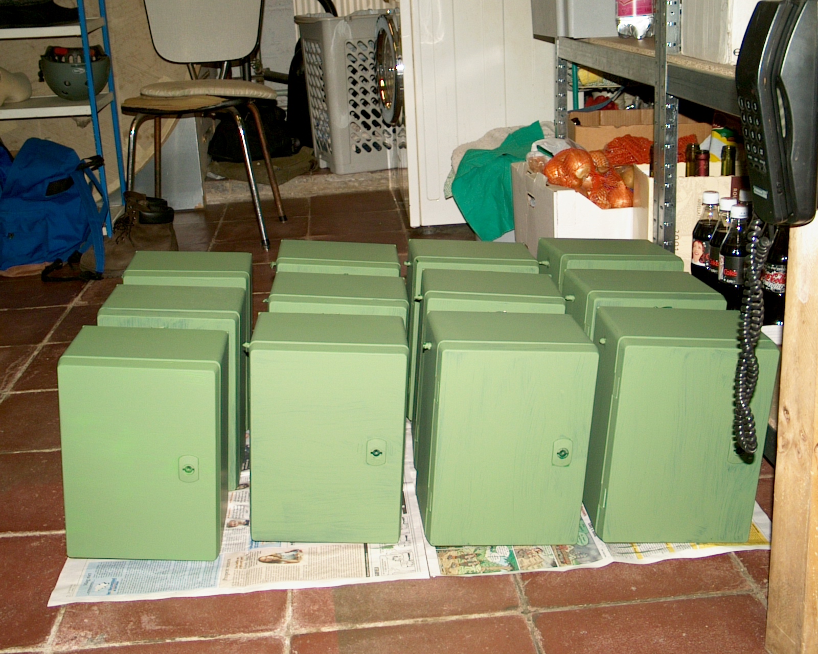 |
Twelve cabinets painted and finished |
 |
A trench 135m long, one meter deep, goes from the tower to the central main cabinet of the triple 4-square. Inside goes 7/8" hardline 50 Ohm cable, a 30 conductor multi-purpose cable, and a 220V line |
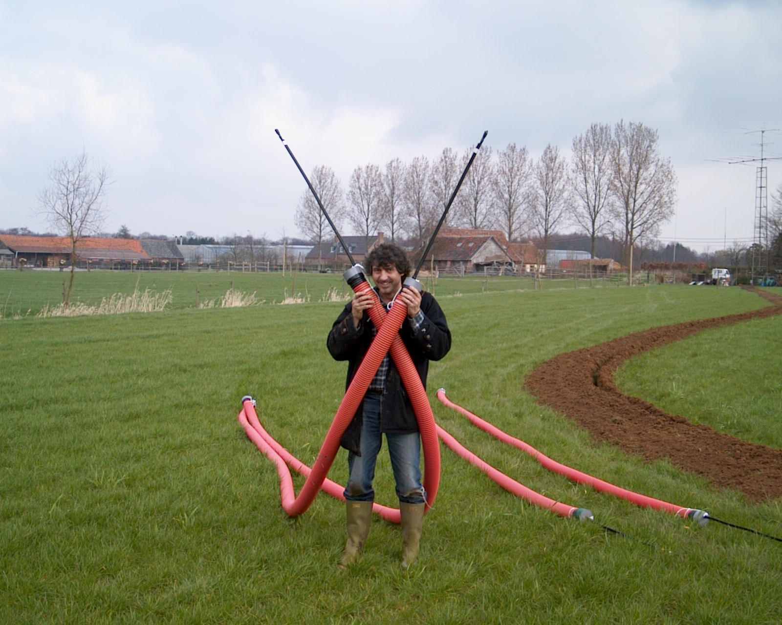 |
Already looking for DX with the 40m feed lines |
 |
All twelve feed lines ready to go below surface. The trench from the tower to the center of the 4-squares is finished |
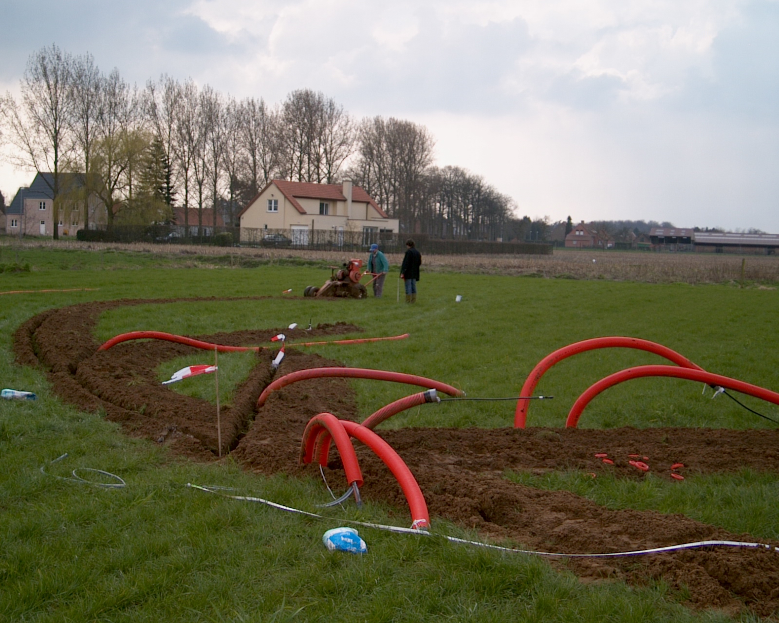 |
40m and 80m trenches for SW direction are finished, and here we are digging the 160m feed line trench |
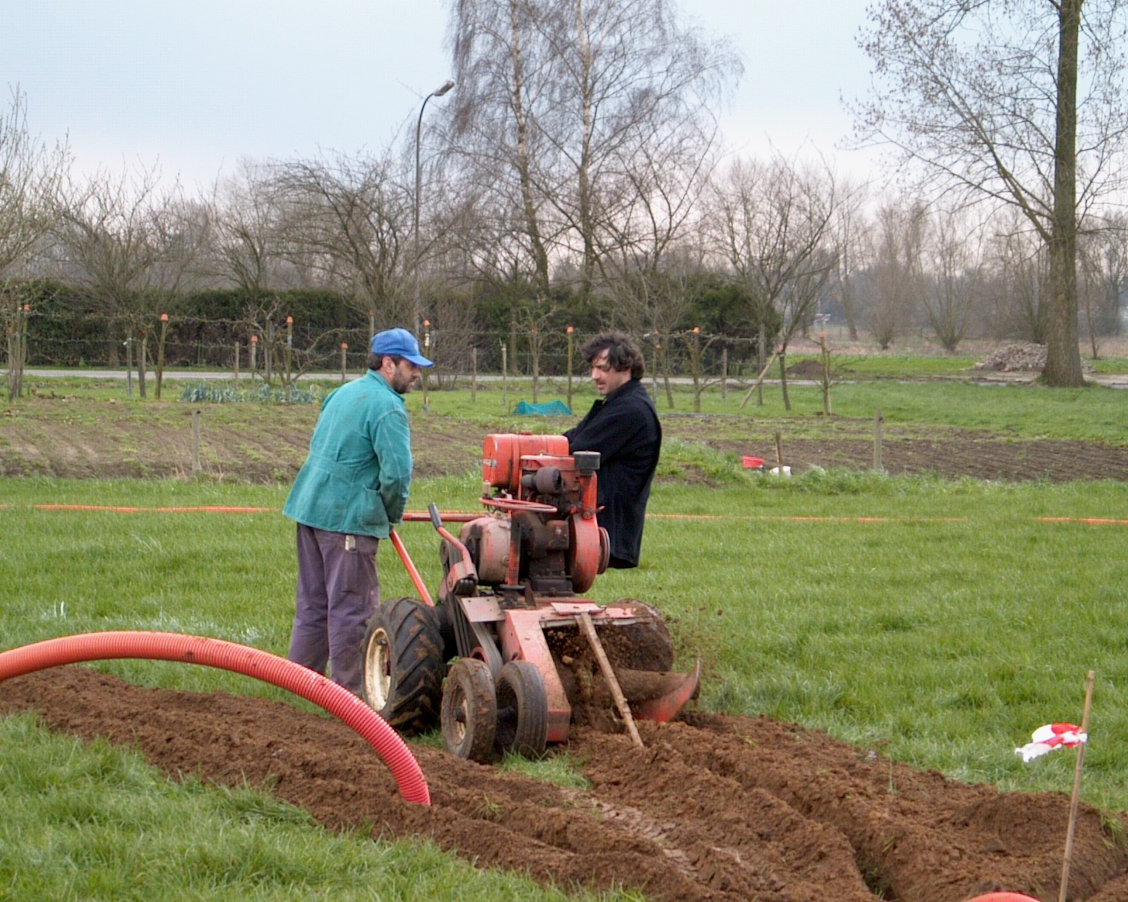 |
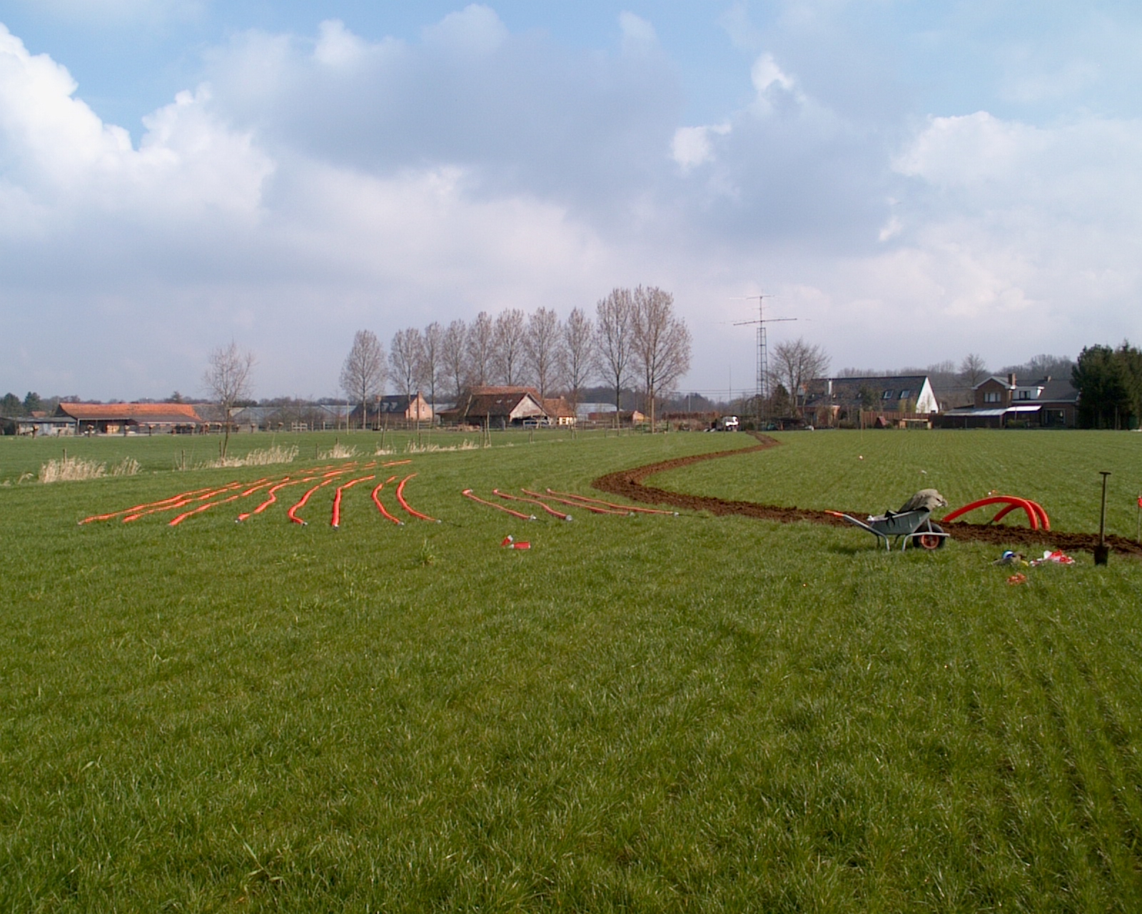
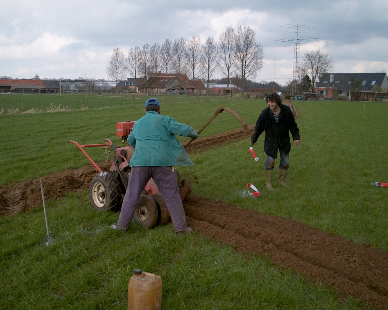
This neat little machine is supposed to dig in straight lines, so we needed some horsepower to bend the curves |
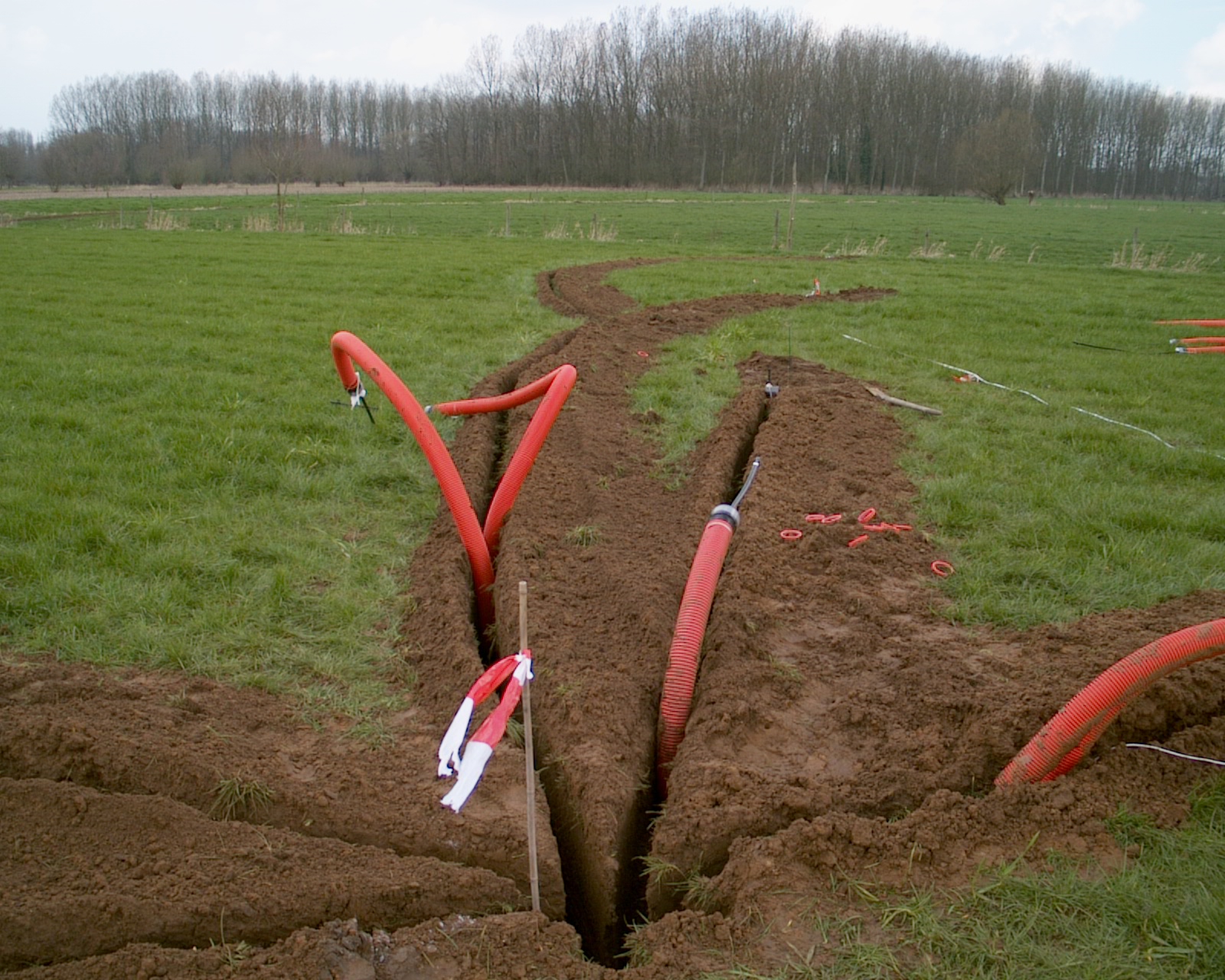 |
NW direction feed lines in place |
 |
After some 500m of digging (at the same time a Beverage coaxial cable was put in a 170m trench), we've reached the finish line |
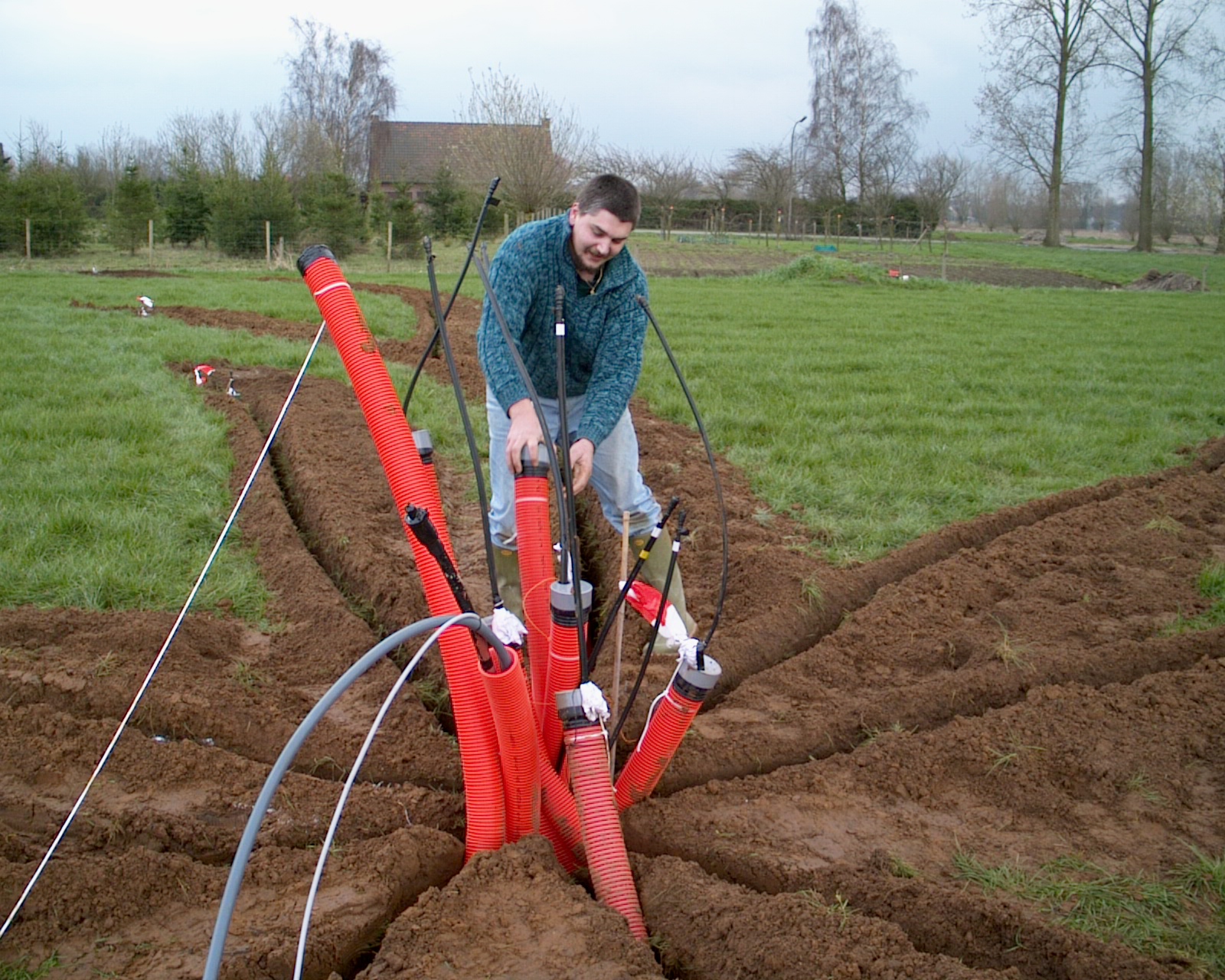 |
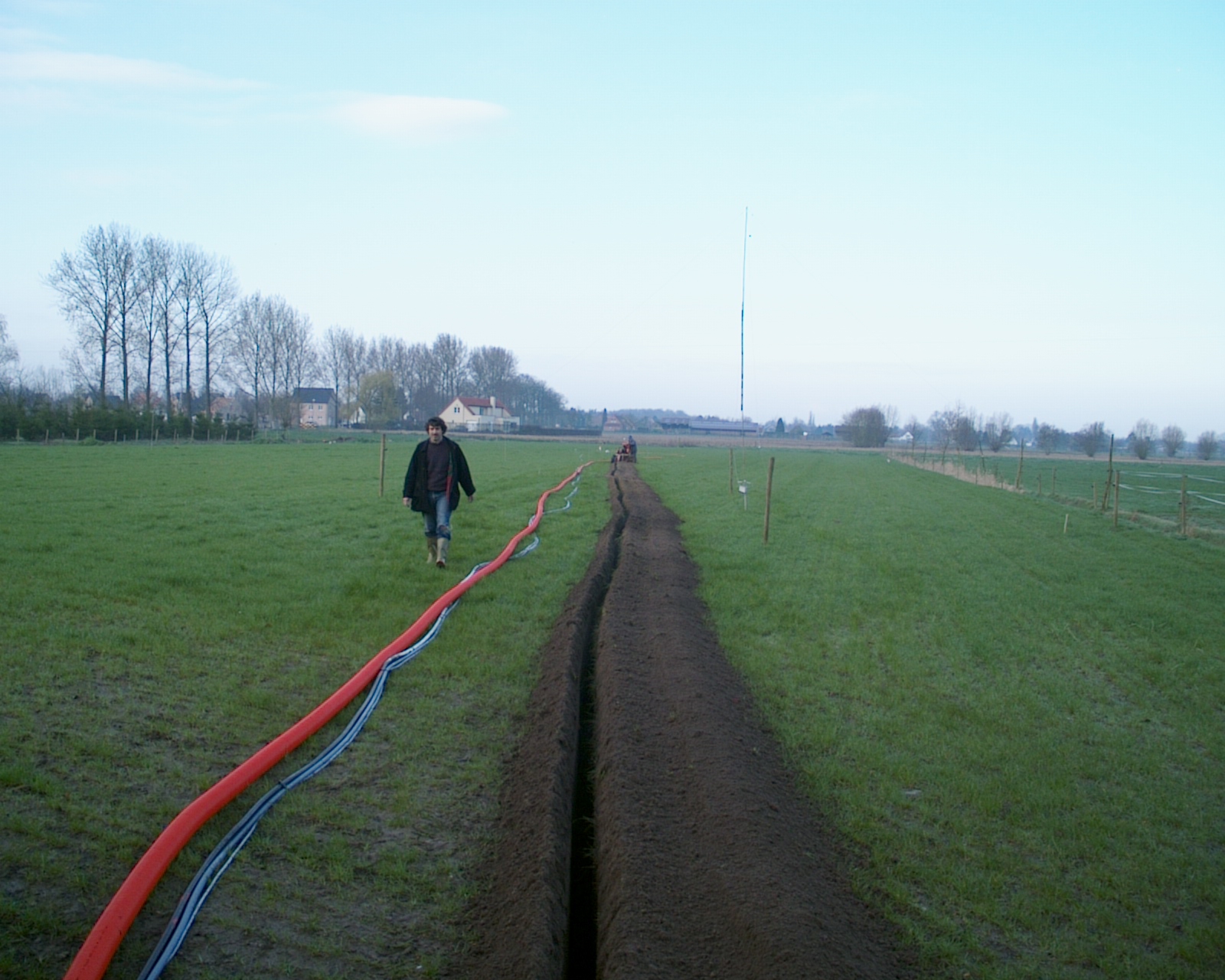
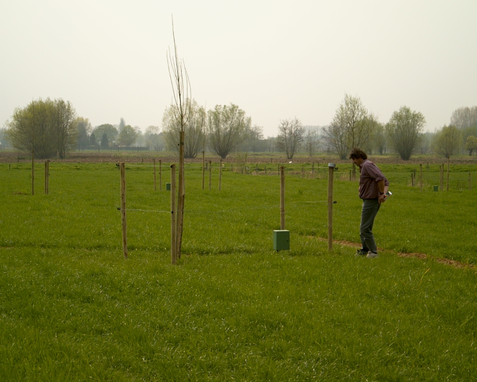
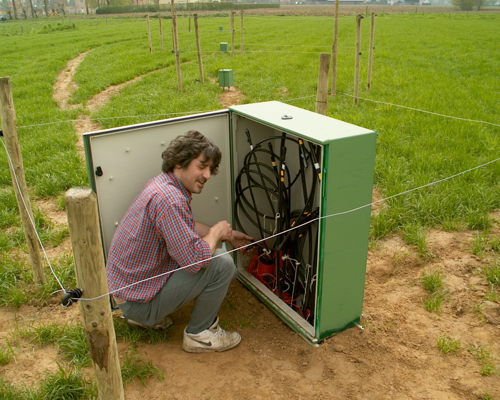
This is Karel ON5TN, who likes electronics, DX-ing, going on DX-peditions
(XU and 6W so far), and who is not afraid of making his hands dirty. Here he's working on the spot where the central main cabinet will come, playing with the feed lines... |
 |
The 40m feed line is visible coming out of the ground, in the direction of the central cabinet |
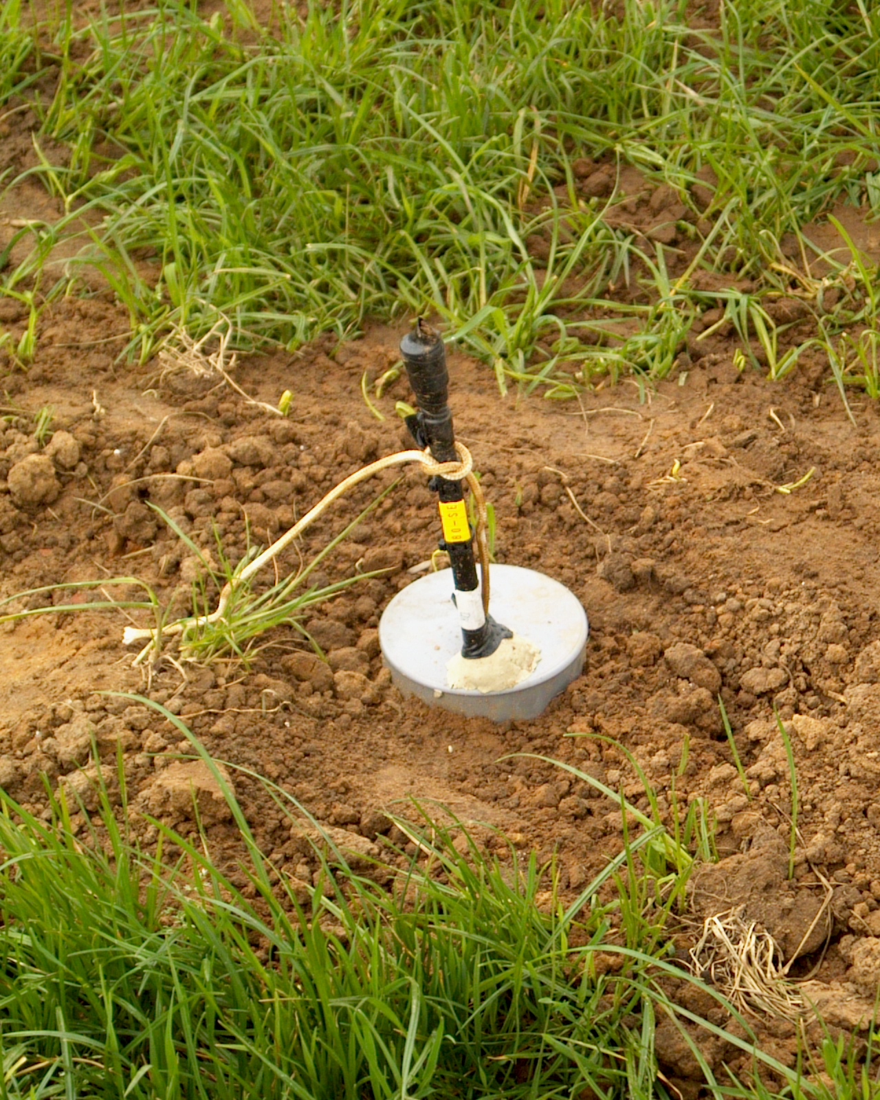 |
This is one of the feed lines surfacing the earth, nicely labelled thanks to Karel ON5TN |
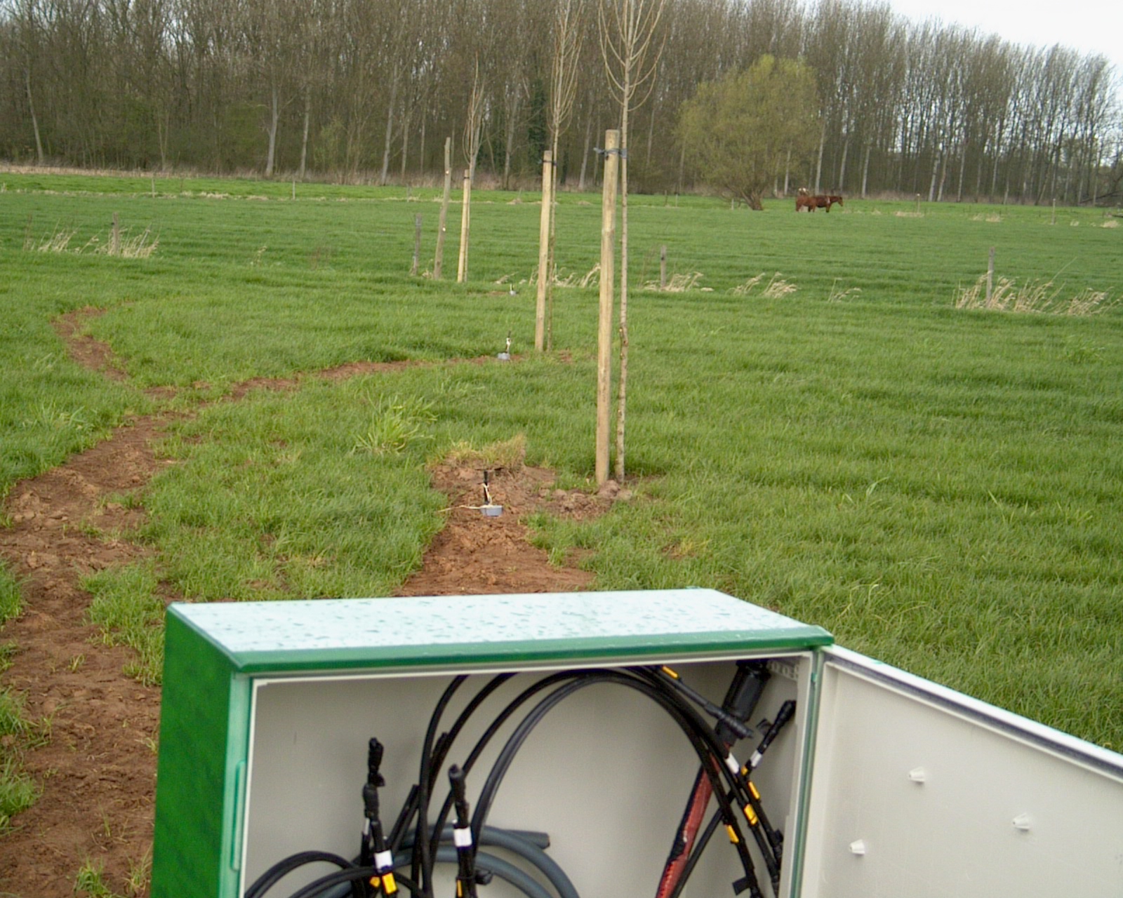 |
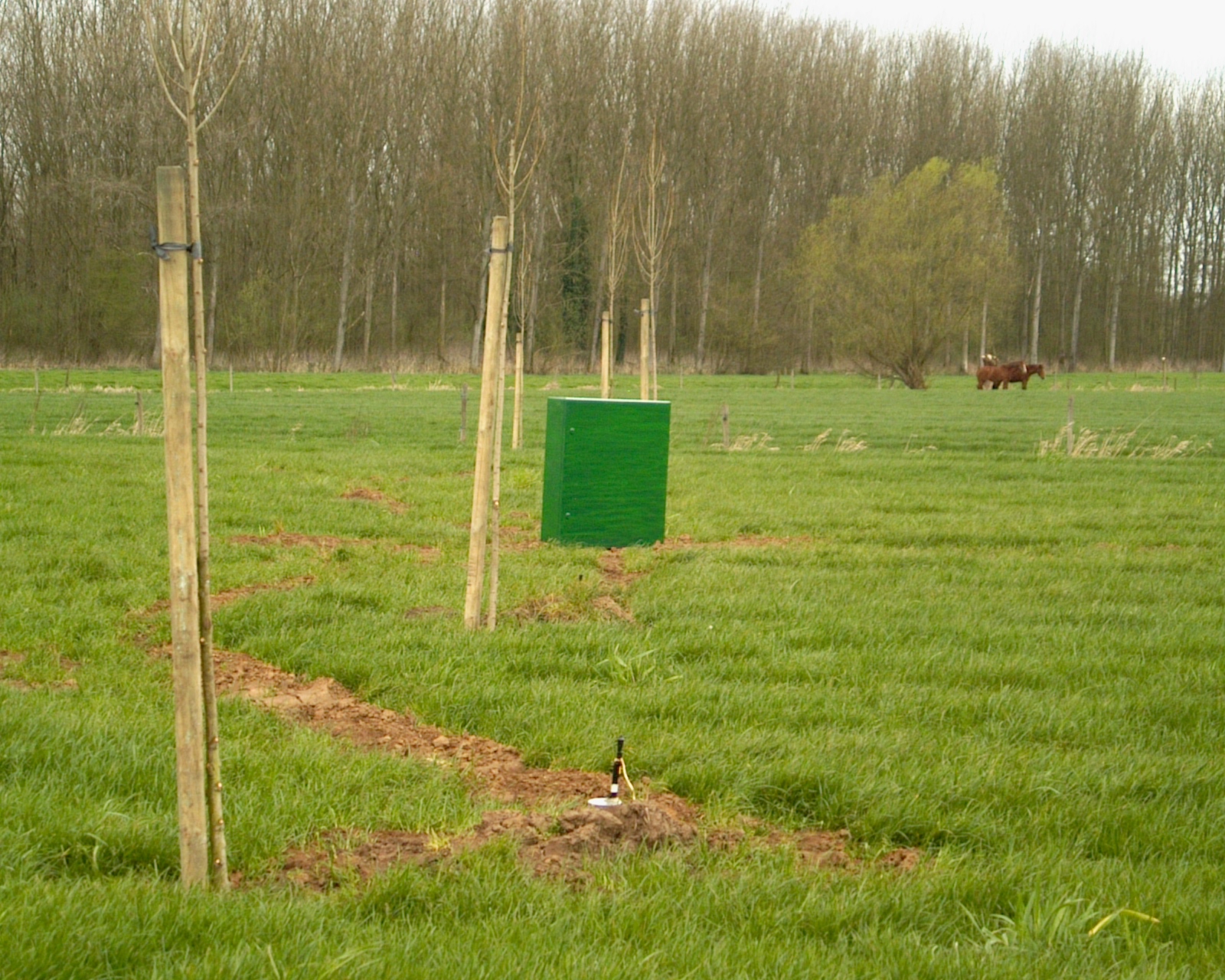
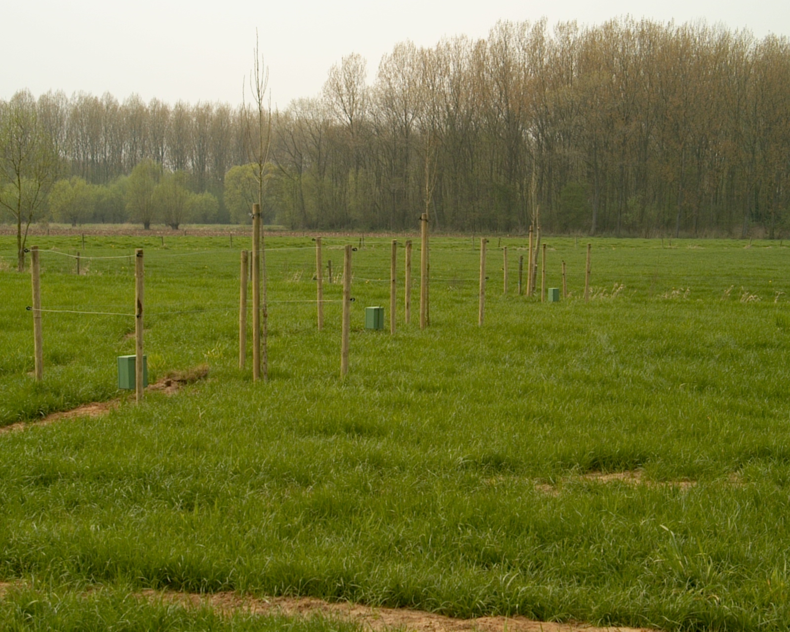
Beyond the open cabinet one can see the 40/80/160m 'trees' and the surfacing feed lines in NW direction |
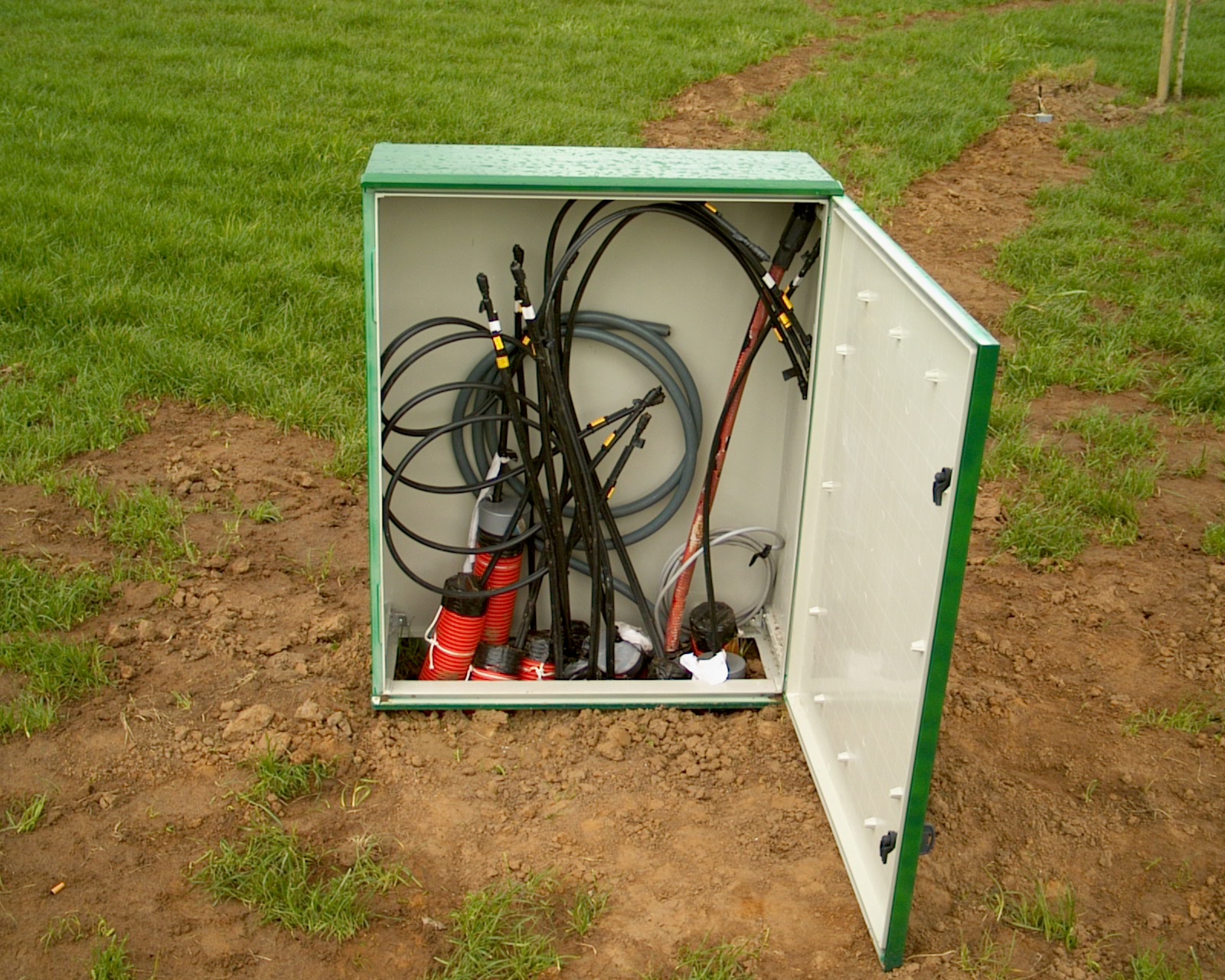 |
Inside the cabinet, we got plenty of time ahead to arrange the cabling and put the hybrid couplers inside |
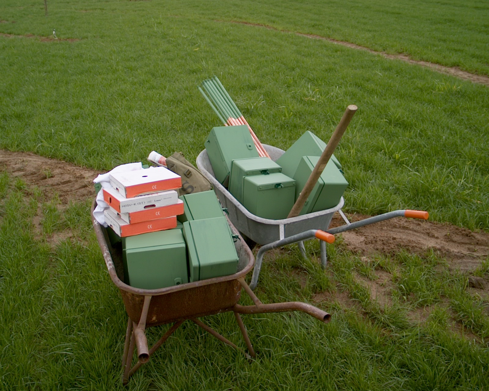 |
The twelve smaller cabinets for the individual 4-square verticals, together
with the twelve ground rods to which they will be attached. Once the verticals will be suspended, ground radials will be attached to the ground rods |
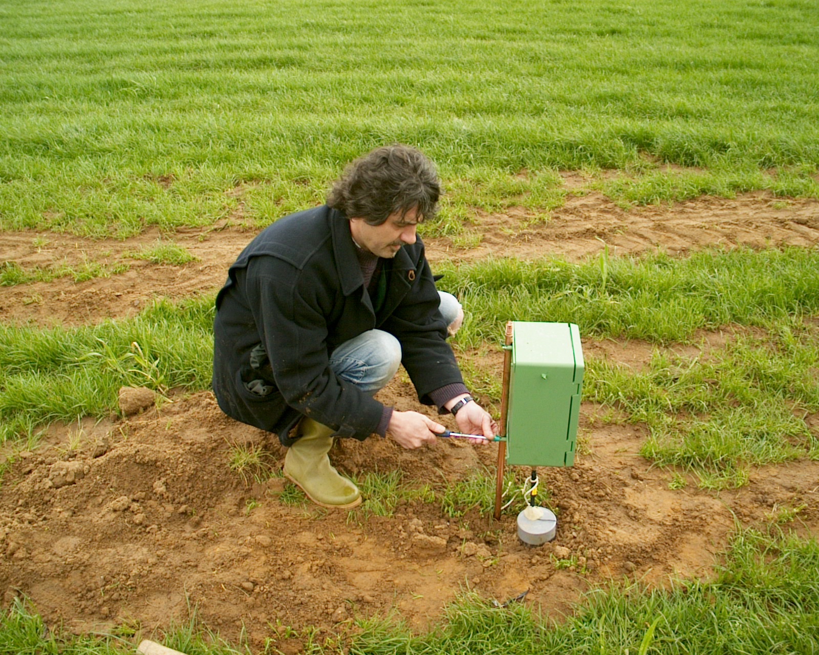 |
Attaching a feed line cabinet to the ground rod |
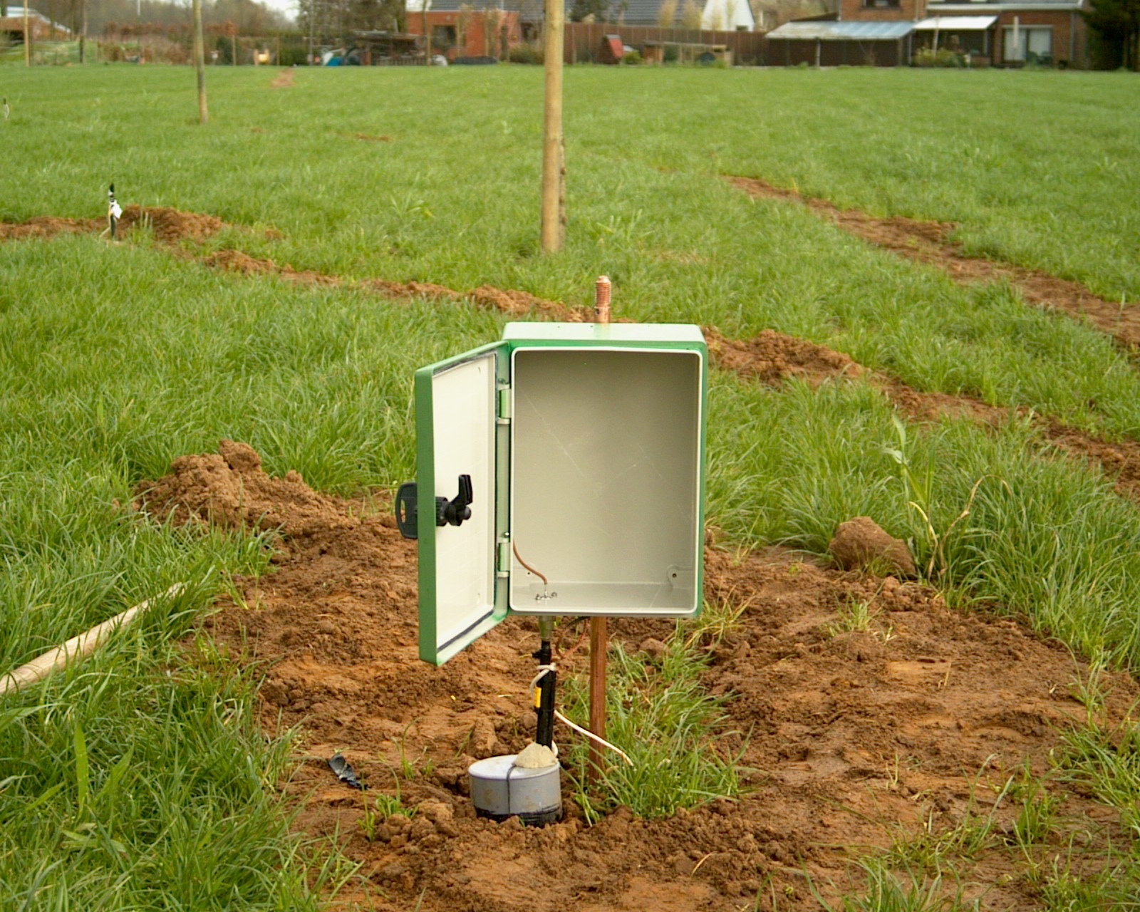 |
Inside a feed line cabinet, lots of space to play around with matching networks |
 |
Each feed line cabinet and its tree is protected with high voltage wires around it, to prevent the summer cattle to damage the construction |
 |
40-80-160m cabinets, trees and high tension protection in NW direction |
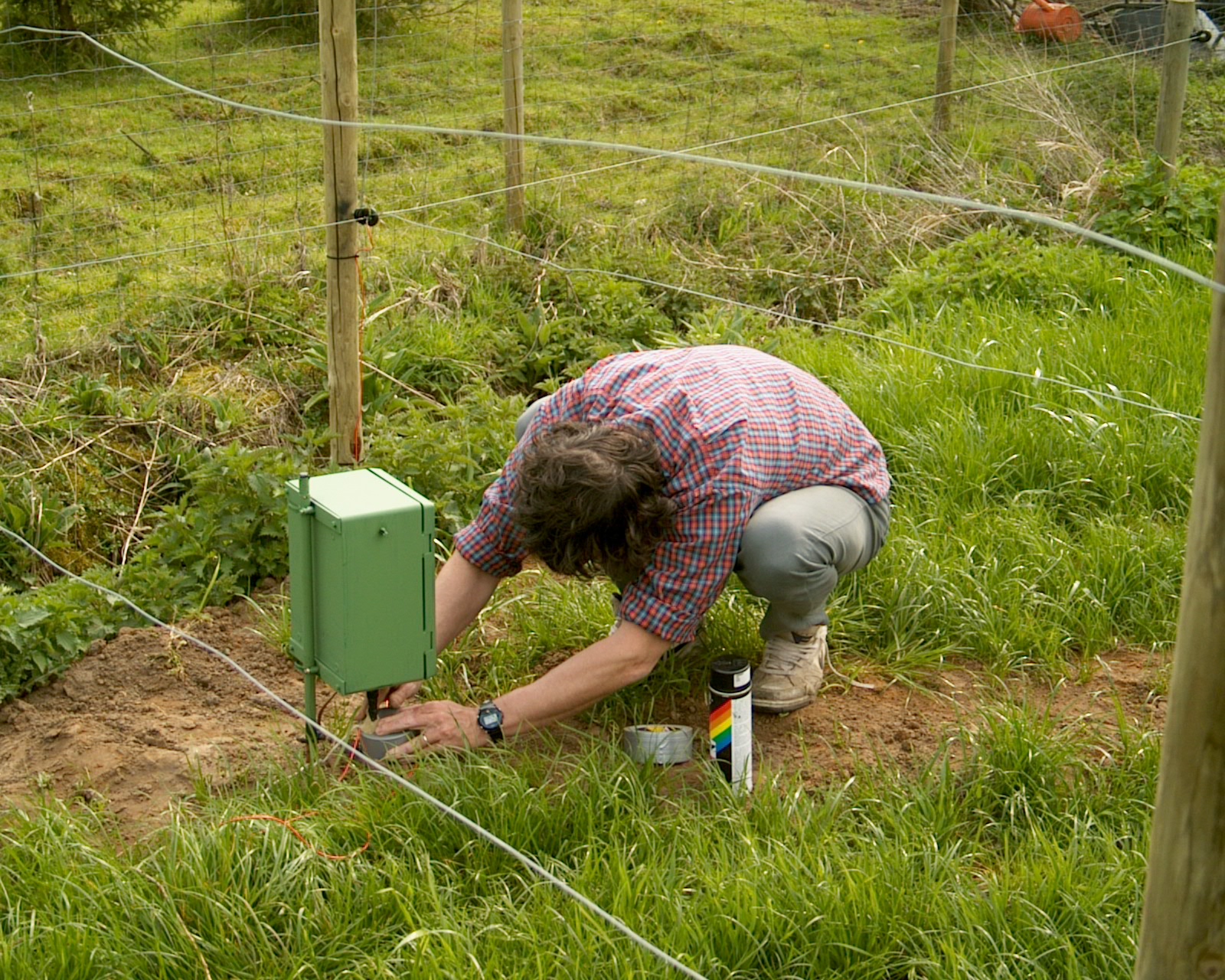 |
Connecting the 75 Ohm feed line to each cabinet and making it waterproof |
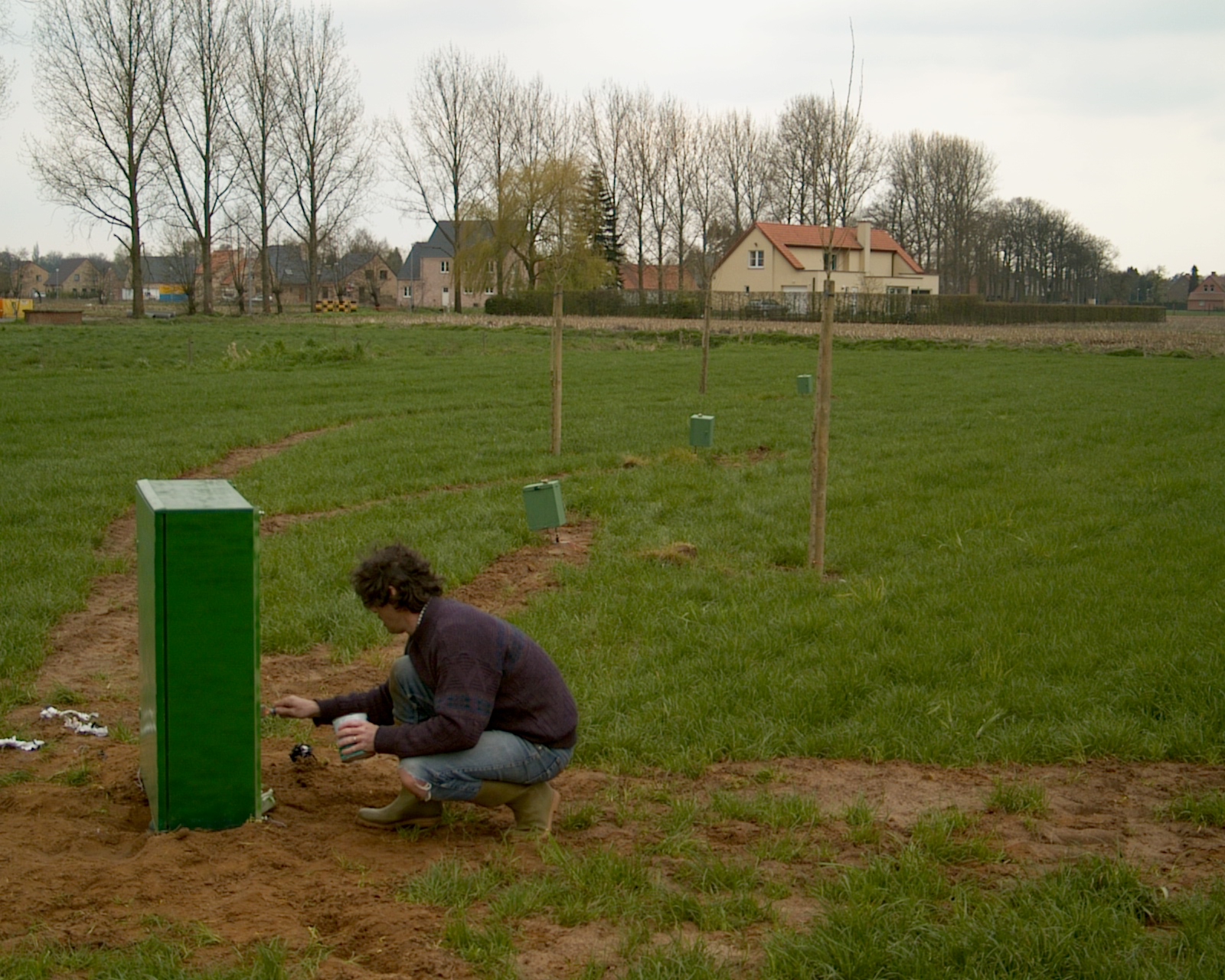 |
Final touch of painting |
 |
No worries, everything is nicely labelled inside the central main cabinet |
| Finalisation 4-square project during 2016-2020 | |
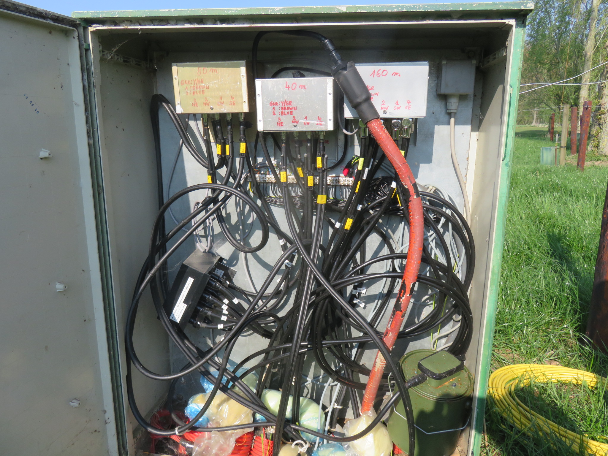 |
Central cabinet with the 3 Comtek ACB-4 hybrid couplers. Bottom right is the dummy load. The black box center left is a modified Ameritron RCS-10X which is used to switch the dummy load between the 3 hybrid couplers (and to use the dummy load as a stand-alone unit) |
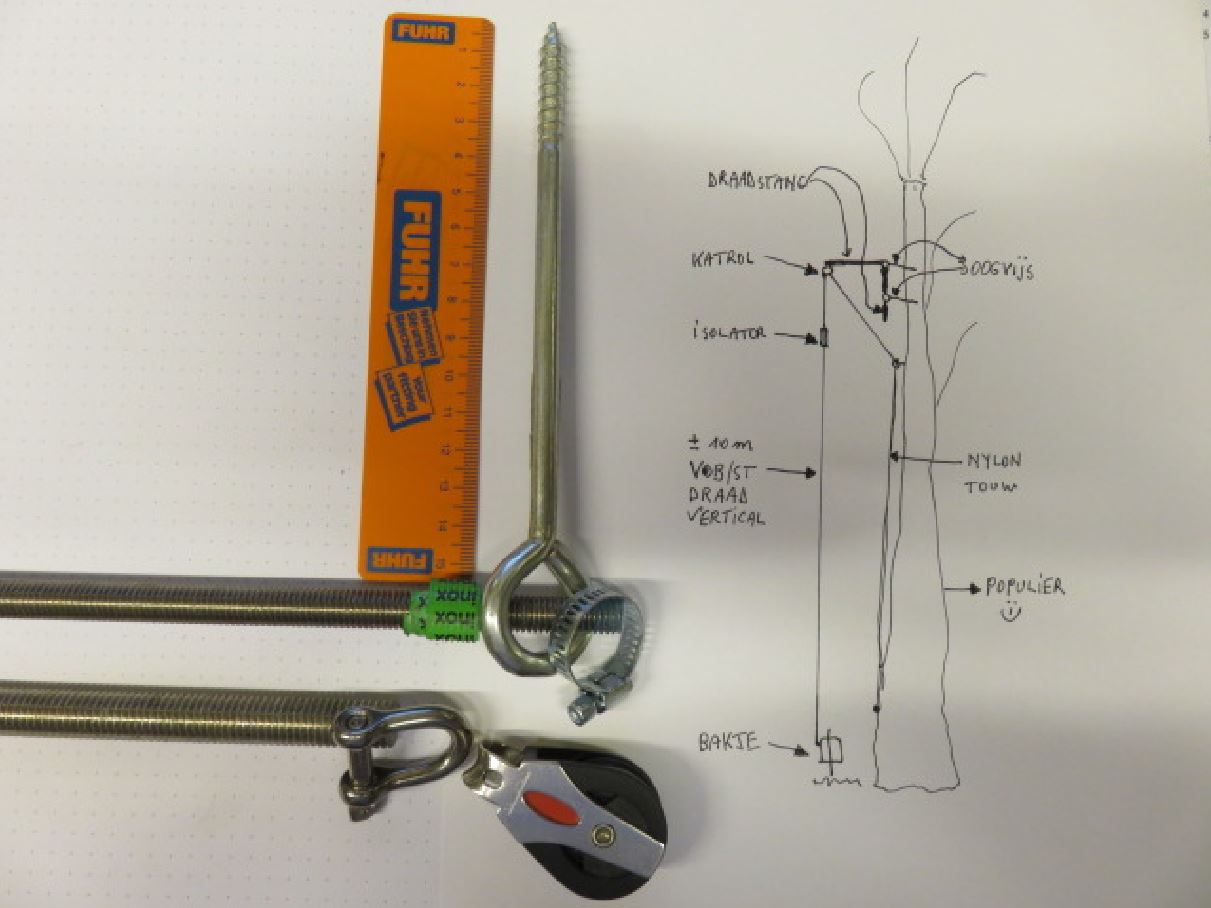 |
This is the initial drawing of the tree support system for the wire verticals. Threaded rod (10mm diameter) of 2m length is partially bent in a 90 degree angle. The 50cm vertical part slides into 2 eye screws, the 1.5m horizontal part supports the wire antennas. About 70cm above the threaded rod, a pulley is attached to another eye screw.The support/hoist rope goes through the pulley and then at the end of the threaded rod through an eye bolt. Friction of the rope in the eye bolt during storm winds made for a couple of rope fractures. The system will be altered whereby the pulley will be installed at the end of the threaded rod. This should prevent rope fracture. The end result will be according to the initial drawing (the drawing misses a support wire above the threaded rod... this support wire is a must to strengthen and keep the rod in place) |
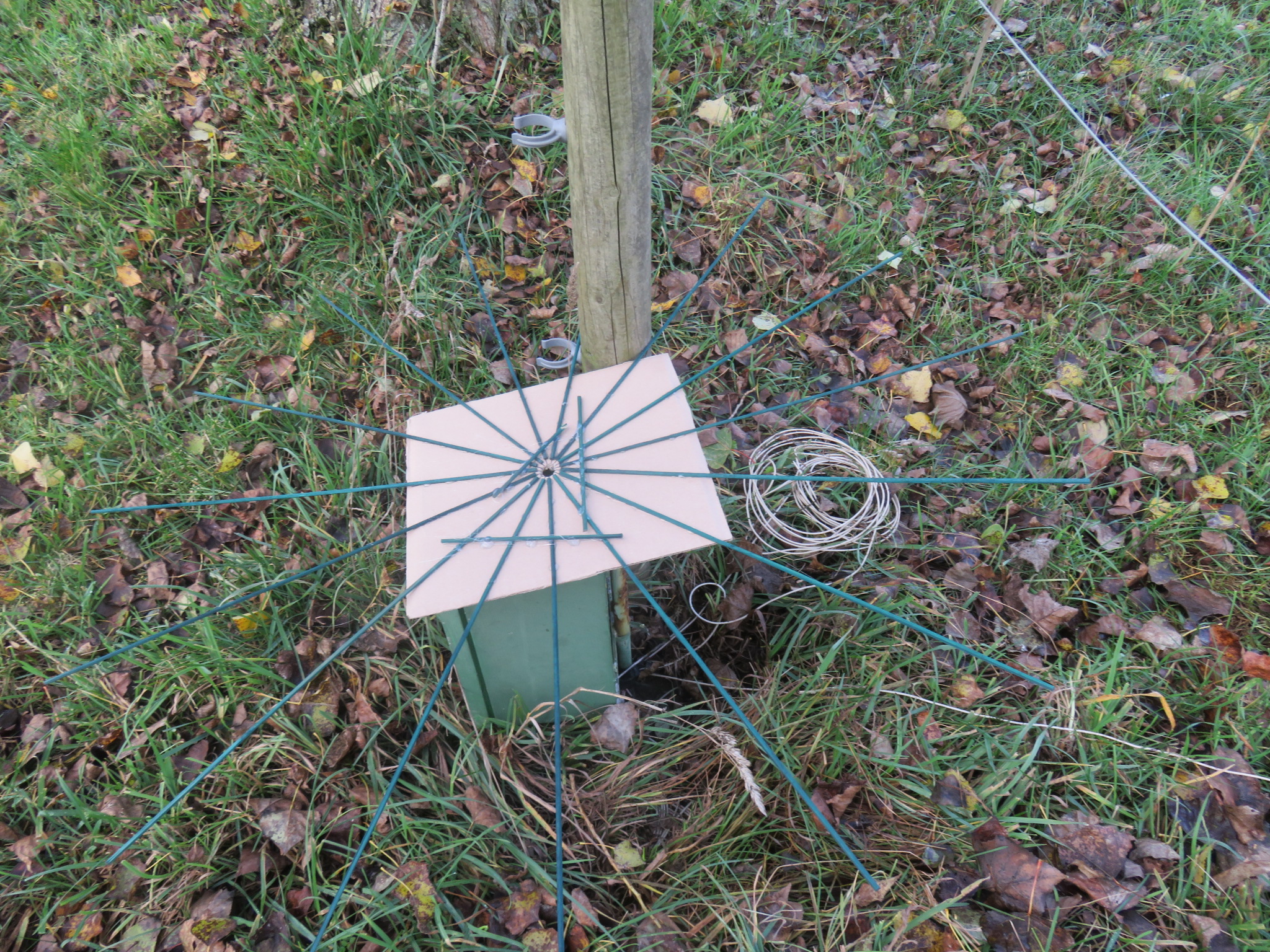 |
This is the template used to lay out the headings of the 15 radials at each vertical |
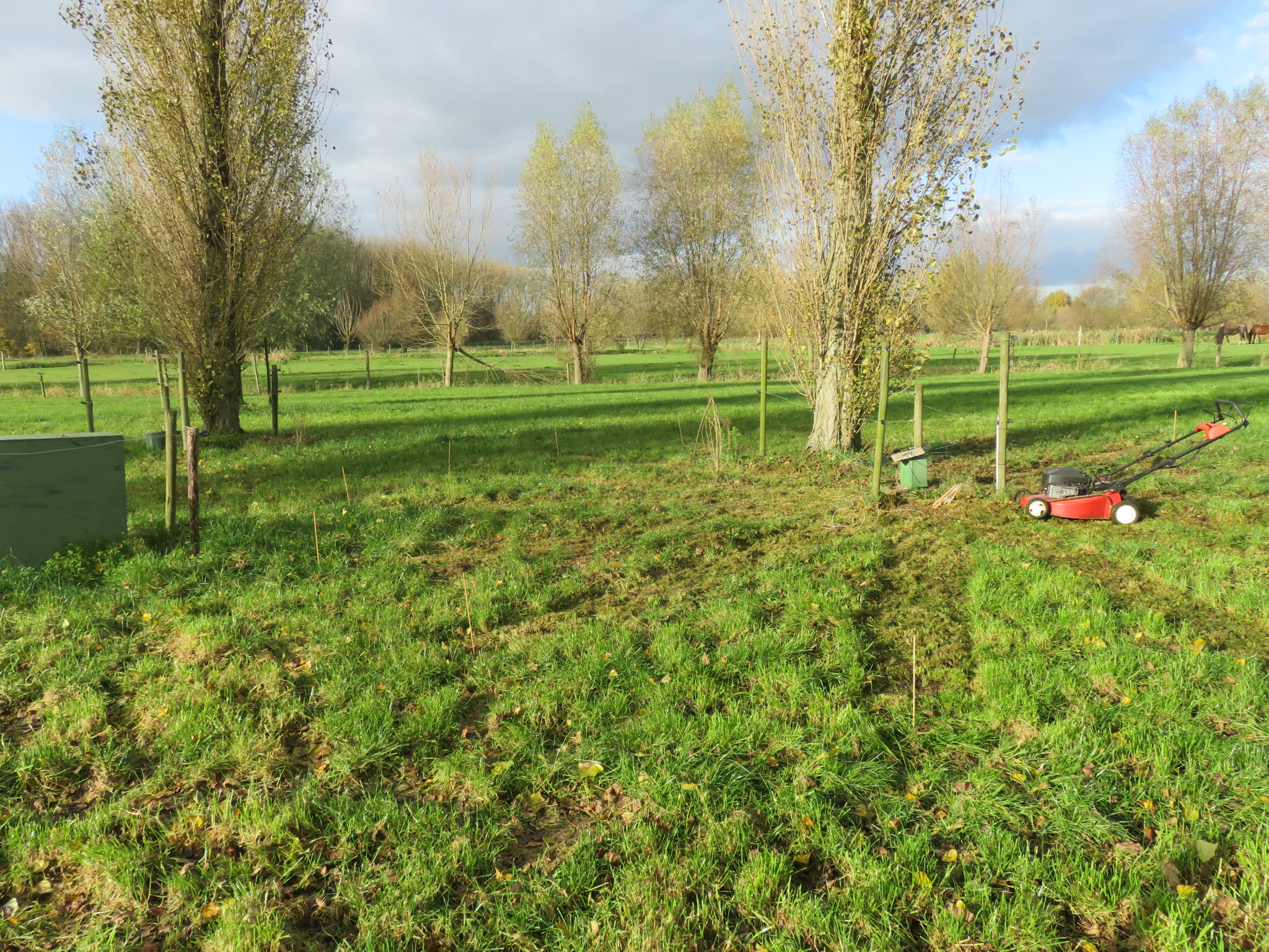 |
Our home lawn mower was used to make the pattern for the 180 radials clearly visible. This visible pattern was a great help for the next step, installing the radials underground. No need to say our small lil' lawn mower didn't withstand the battering on the uneven field very well... halfway through, it had to go in for repairs |
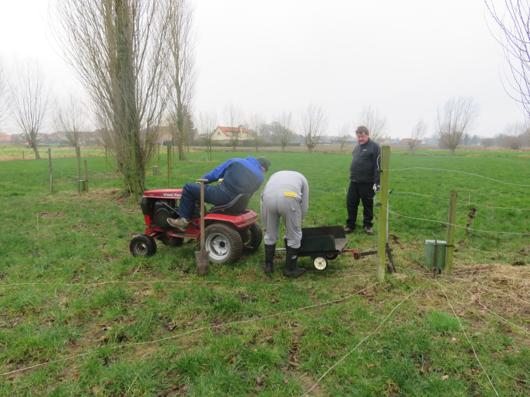 |
Here's the Wheel Horse of on1bej's dad. Patrick on7asn made a cutting device with wire-guide. This device at first had 1 cutting blade, this attempt was not successful. A smaller cutting blade was then installed in front of the heavy blade. With 2 cutting blades and heavyweight hams on top of it, the hard soil could be penetrated and the radials went smoothly 10cm underground. Here's a movie of instalment of an 80m radial, and this movie for a 160m radial (underground tree roots were not helpful...). No need to say 180 radials took a while to get underground... Kudos go to on1bej, on5tn, on6yn and on7asn...tnx guys! |
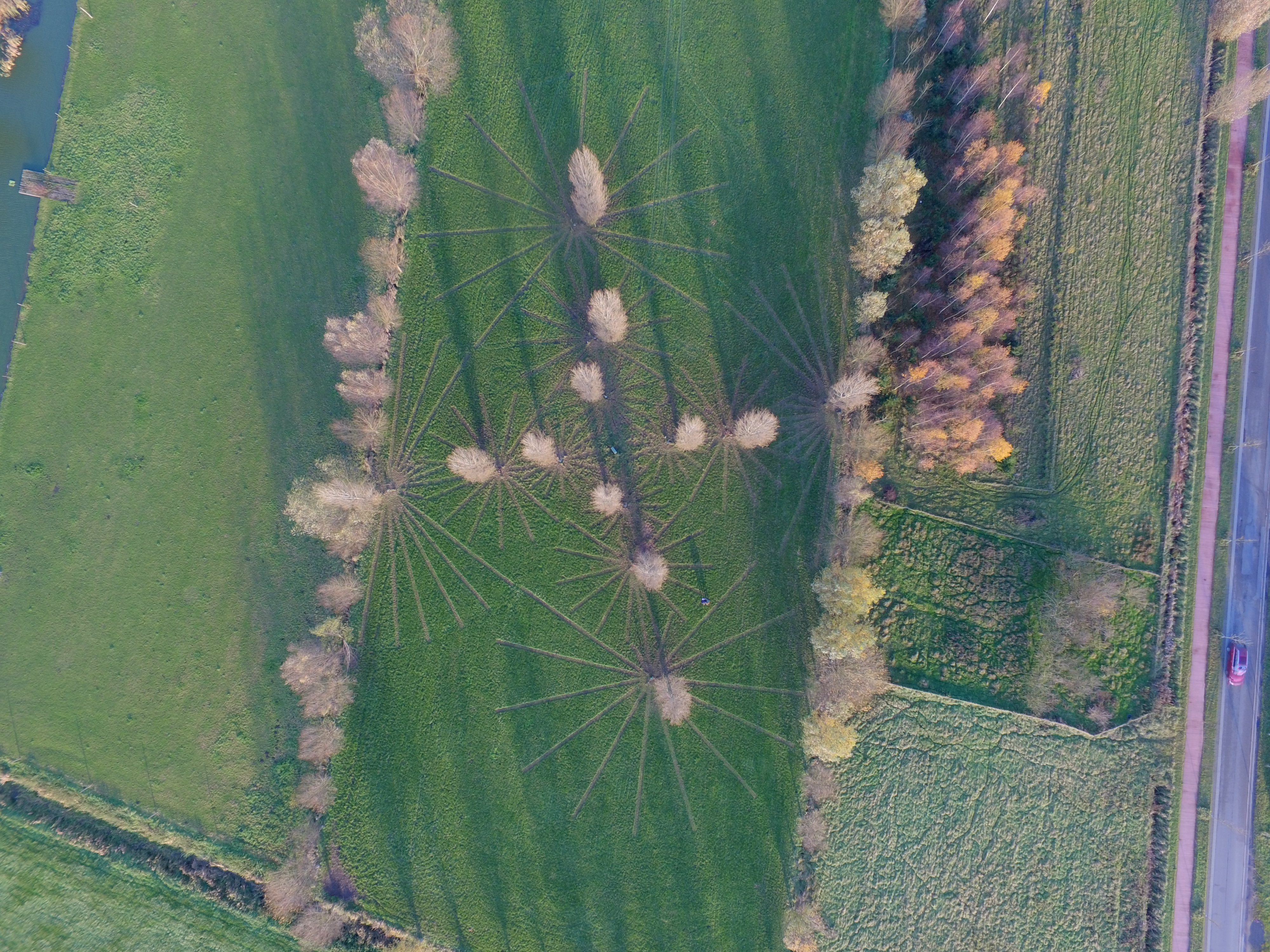 |
No, the aliens have not landed. This is an aerial overview photo of the radials' pattern (made visible with the lawn mower). This photo was taken with a drone, tnx to on4aed |
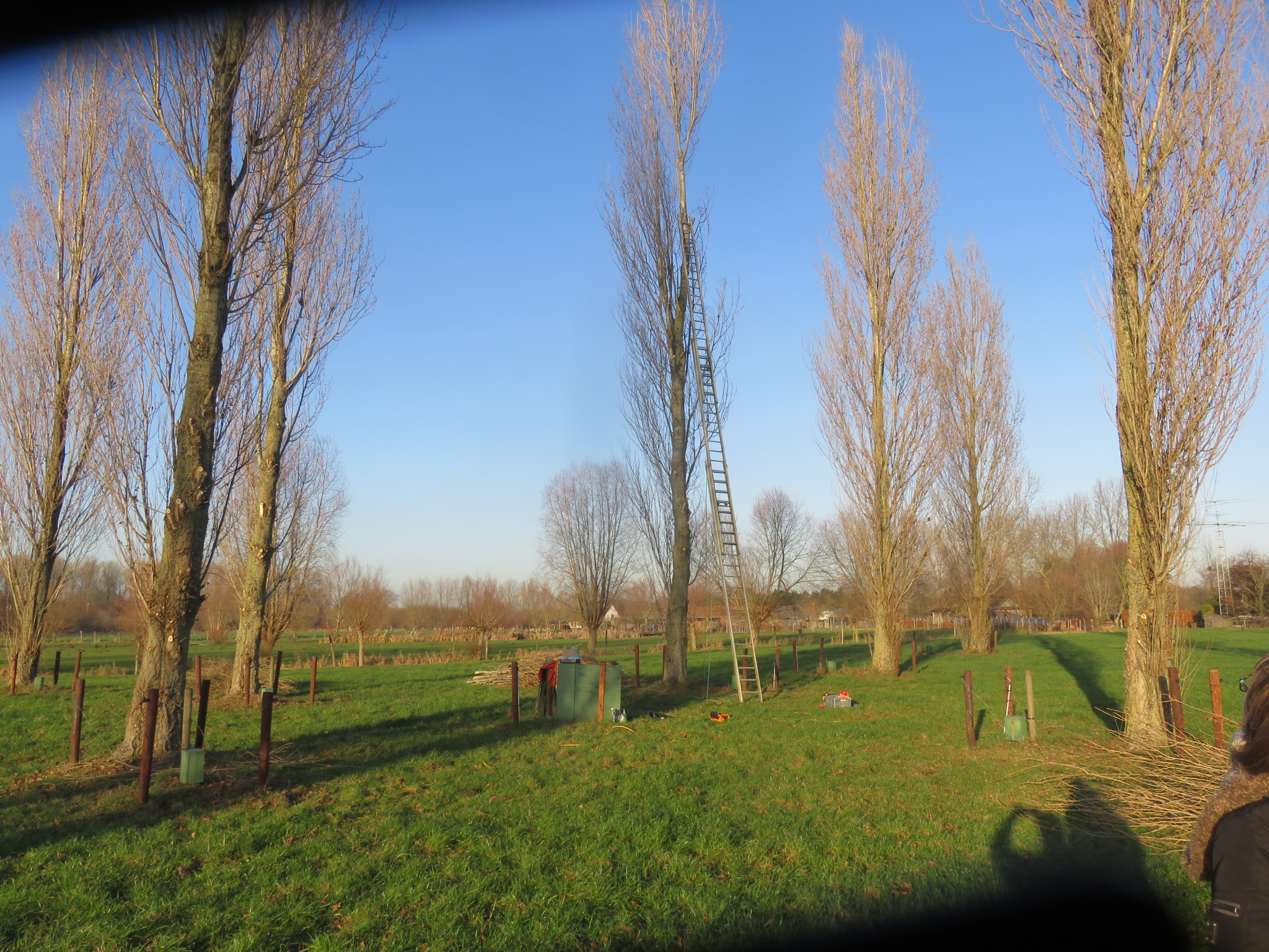 |
Time to install the antennas. I bought a second hand heavy duty 15m construction site ladder. This turned out not to be a good idea. Together with on4ma, the two of us managed to install one 40m vertical with great difficulty. After instalment of the 2nd 40m vertical, things went bad when lowering the ladder. Destroyed antenna, end of exercise. Time to get sensible and get a mobile elevating work platform... |
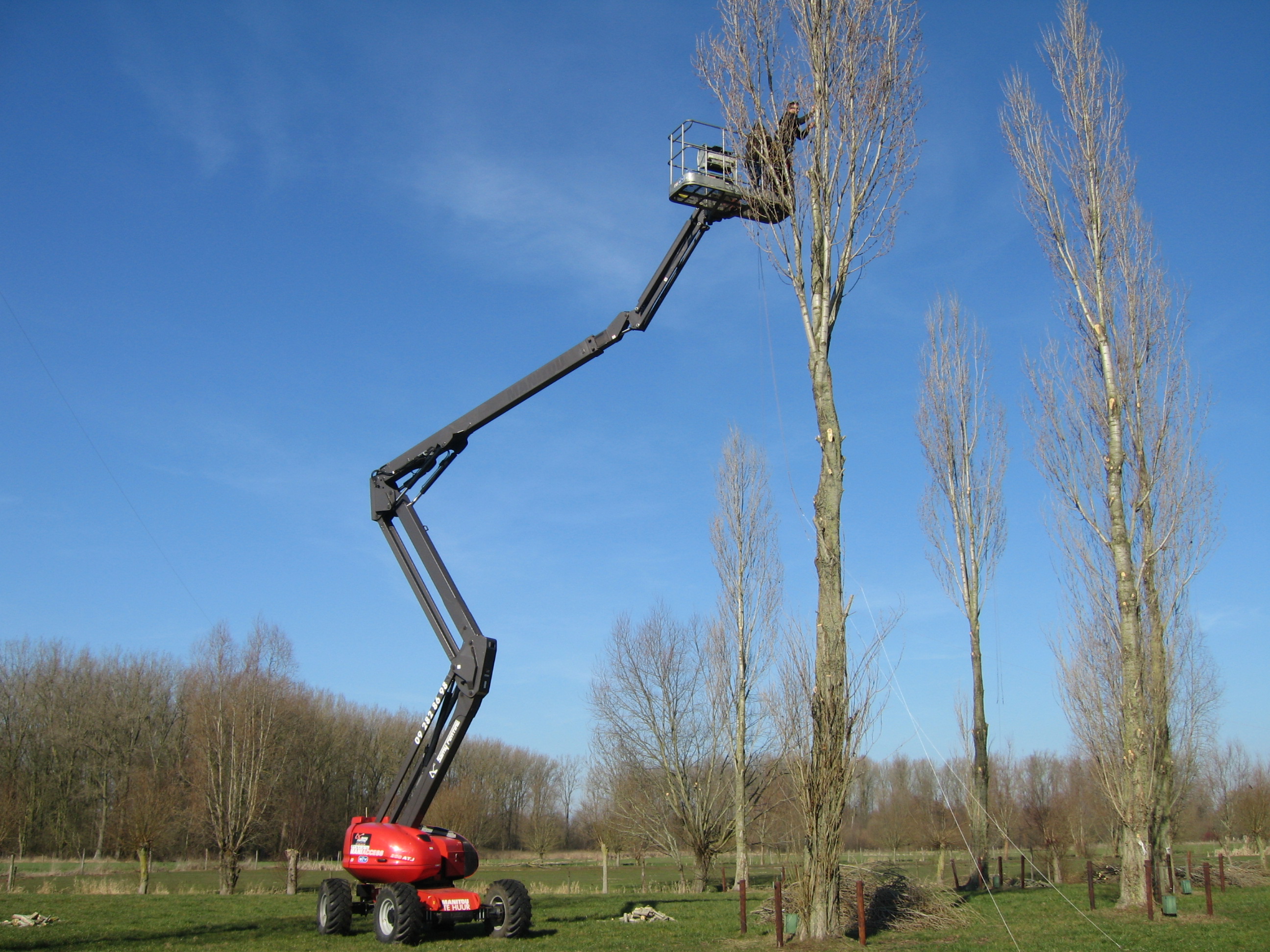 |
Now we're talking. My son Mark jr. and Marc on4ma are at 12m height installing an antenna. Mark jr. has operated this kind of equipment since his teens. Tnx guys! |
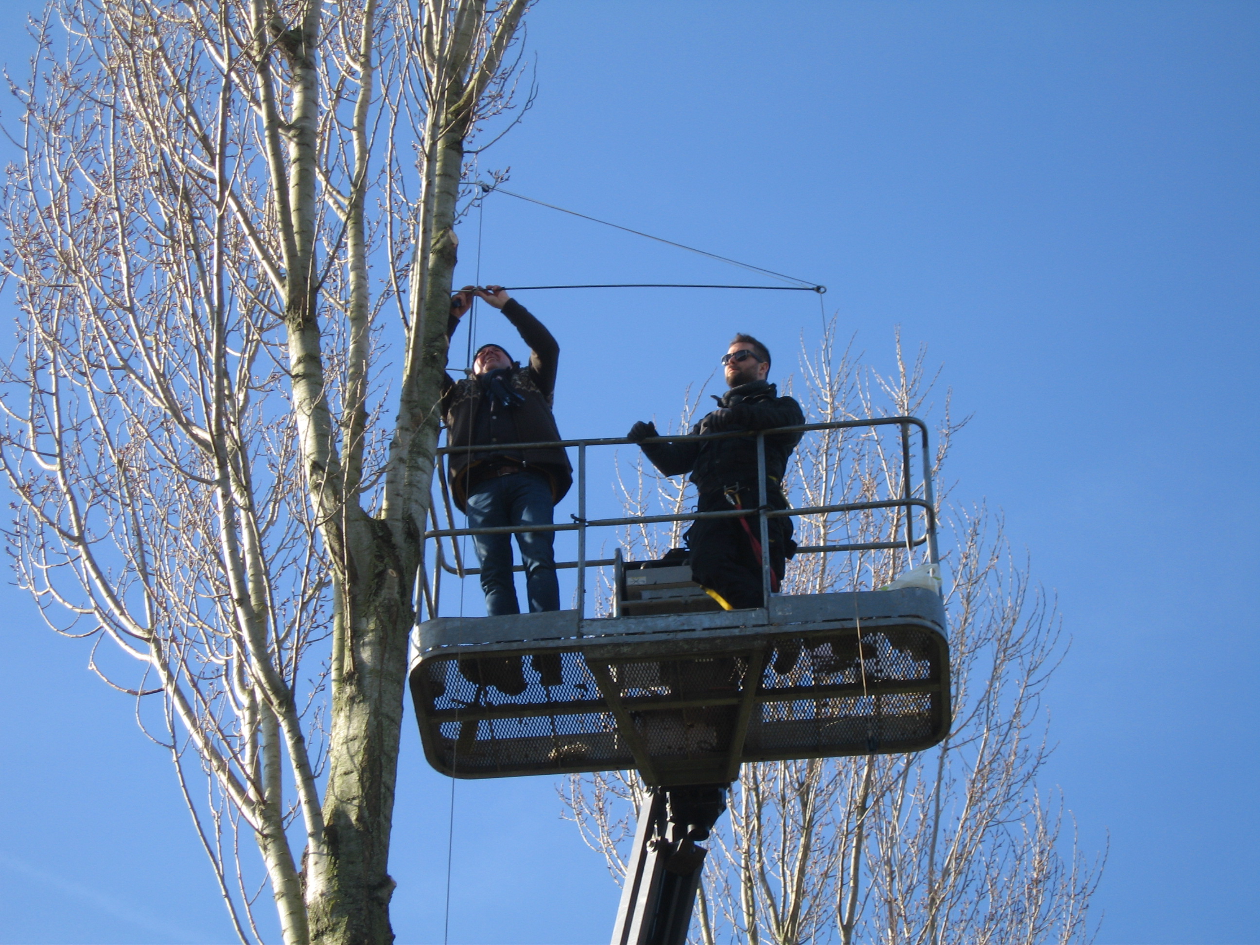 |
Closeup of Marc and Mark installing one of the antennas. Note the 50cm part of the threaded rod attached inside 2 eye screws, the pulley attached to another eye screw about 70cm above the threaded rod, and the antenna support wire going downward from the pulley through an eye bolt at the end of the threaded rod |
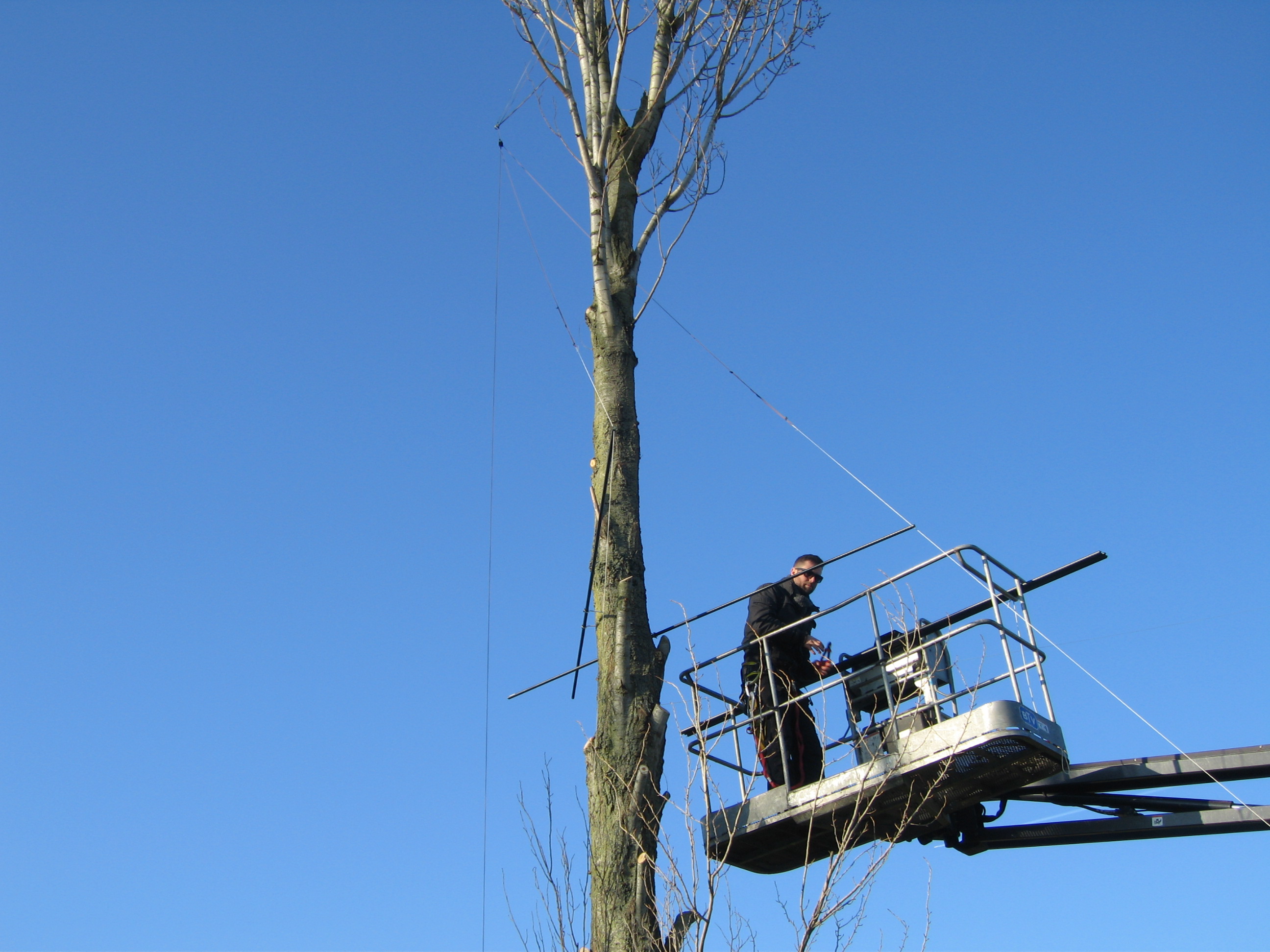 |
This picture shows an 80m shortened vertical with capacitance hat. Note the legs of the capacitance hat being pulled back behind the tree, and close to the tree |
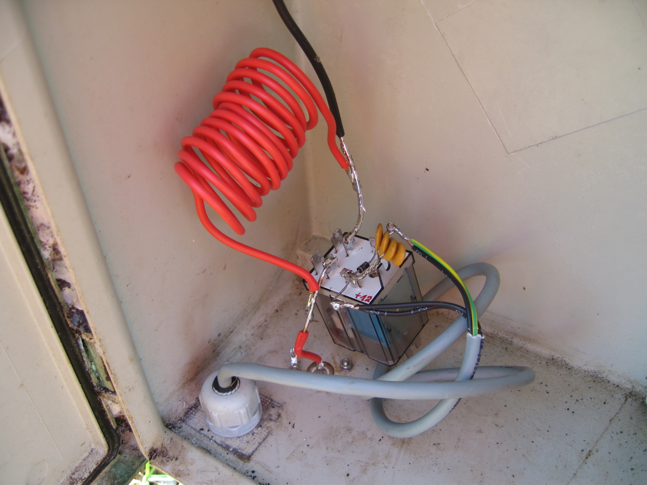 |
To switch from SSB to CW, at the bottom of each 80m vertical a 2.465uH coil is switched in with a relay (Finder 65.31.9.012.0000). This is installed in this type of cabinet. Luc on5uk was instrumental in calculating the different L and hairpin matching networks I tested for the 80 and 160m verticals...tnx Luc! |